Balloon unit is a term used to describe the entire system, except the payload. This includes the balloon itself, an emergency cut-down system, the parachute, a radar reflector, and the tracking beacon. The balloon unit should be capable of carrying the payload to an altitude of approximately 100,000 ft where the balloon will burst. At this point the parachute should be sufficient to deliver the payload safely back to Earth. Throughout the entire flight, the beacon will be transmitting the systems location to allow for an easy recovery of the payload once the flight has been completed.
The proven and most logical configuration for the entire system is the one seen in the photo of a balloon satellite, launched by the Borealis group in Montana, below.
Figure 6.1.1: Balloon Unit Configuration [Borealis]
(cut-down system and radar reflector not shown)
As seen above, the most obvious configuration is the balloon at the top of the system, with the cut-down system and parachute, already deployed, directly beneath it, followed by the radar reflector and parachute ring, the tracking beacon, and, finally, the payload. In such a configuration, it is unnecessary to use a parachute deployment system since the parachute is hung pre-deployed beneath the balloon. This feature greatly simplifies the design of the system as a whole. Details of each component of the balloon unit will be discussed in descending order from the top of the configuration, in the following sections.
In the fall of 2003, a group of aerospace engineering students at the University of Texas at Austin, [Wang], performed research into the type of balloon needed to meet the objectives of this project and researched balloon manufacturers and vendors which could provide such a balloon.
The previous group’s research has determined that a helium-filled, totex balloon will be ideal for meeting all of the project requirements. Totex is, essentially, a stronger, thicker, more durable derivative of latex and is used by nearly all the balloon manufacturers which were researched. They also determined that the actual amount of helium required can be determined by using the following equation:
|
|
|
1 |
where V is the volume of the balloon, assumed to be spherical, ρair is the density of air at sea level, ≈ 1.225 kg/m3, ρhelium is the density of helium at sea level, ≈ 0.169 kg/m3, g is the gravitational acceleration at sea level, ≈ 9.81 m/s2, Cd is the drag coefficient, ≈ 0.3, A is the surface area of the balloon, v is the ascent rate, mpayload is the payload mass, and mballoon is the balloon mass.
As a follow-up to the previous group’s research into balloon manufacturers, we also contacted three different companies, Kaymont, Kaysam Worldwide Inc., and Raven Industries. Using the total payload and beacon mass model of roughly 18lbs, and all of the information acquired from the three companies, it was determined that a Kaymont, 3000 gram balloon would be the ideal balloon for our mission. This particular balloon has a barely inflated or flaccid diameter of 2.27 m, a bursting diameter of 13m, and a bursting altitude of 37.9 km or 124,000 ft with a cost of $225. Below is a picture of actual balloon purchased, still in its original package, from Kaymont Meteorological Balloons.
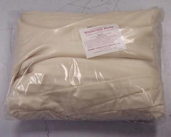
Figure 6.2.2.1: 3000g Meteorological Balloon Purchased from Kaymont
Using Equation 1 and the dimensions of the Kaymont 3000g balloon, we determined that the balloon would require roughly 1900 ft3 of helium to deliver the payload to an altitude of at least 100,000 ft. This value seemed to be a bit higher than initially thought. To determine if this was the correct value, we contacted the Edge of Space Sciences (EOSS) group in Colorado, who has vast experience with launching and recovering high altitude balloons. Their belief was that we would only require half of the calculated amount of helium and offered a much simpler method for the solution of this problem. Through experience, EOSS has determined that filling a sandbag with approximately 120% of the total mass of the system, including the balloon and the parachute, and then filling the balloon until the sandbag begins to lift off the ground, will lend enough helium to generate an ascent rate of 1000ft/s.
The helium was purchased from the cryogenics lab in the RLM at a cost of $57.40/220ft3. At this price and volume, the mission would require five canisters of helium, seen in Figure 6.2.3.1, for a total cost of $287.00.
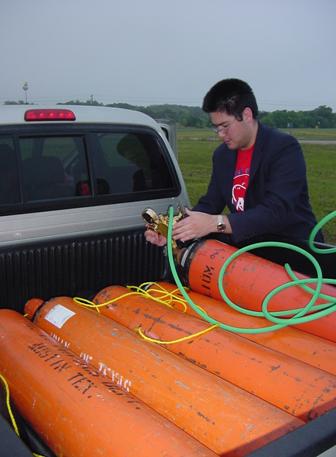
Figure 6.2.3.1: Helium Tanks Needed to Fill Balloon
The Balloon will be filled at the launch site since it would be far too difficult to transport a full balloon to the site. To actually fill the balloon with helium an adapter is needed since the nozzle of the helium regulator is much smaller than the opening in the balloon. The following apparatus was designed and built as a solution to this problem.
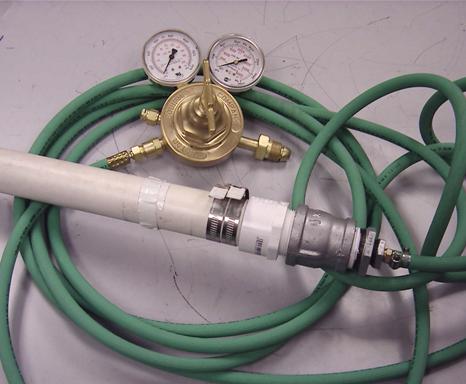
Figure 6.2.4.1: Adaptor Built to Fill Balloon
The adaptor is simply a piece of PVC pipe which is approximately the same diameter as the inlet of the balloon. To connect this PVC pipe to the hose, another simple adaptor was used to which allowed the much smaller hose to screw directly into the PVC pipe. When filling the balloon this PVC pipe will be inserted into the opening in the bottom of the balloon. Once filled with the correct amount of helium, the balloon will simply be tied off, much like a regular, rubber, party balloon. The rope attaching the balloon to the rest of the system will then be tied around the knot in the balloon. To ensure that the rope does not slip off of the balloon the excess totex now hanging off the base of the balloon will rolled up on itself several times then taped to form a lip which will not allow the rope to slip, which would release the balloon prematurely.
The Federal Aviation Administration (FAA) requires that any unmanned balloon must be equipped with two independent payload cut-down systems [FAA Regulations]. As seen in the schematic below, an 80lb test fishing line is looped through two support rings, one connecting the cut-down device to the balloon and the other connecting to the rest of the system. The NiCr wire is wrapped around the fishing line loop and connected to the cut-down relay switch.
Figure 6.3.1: Rough Schematic of Cut-Down System
For BalloonSat, the two cut-down systems employed are a timing and Dual Tone Multi Frequency (DTMF) circuit. Both circuits are housed in the beacon; therefore the details of each circuit will be discussed in association with the beacon hardware. When one of the circuits is triggered, it sends a current though the NiCr wire which then burns through the fishing line, releasing the balloon and allowing the payload to begin its descent back to the ground. Below is a photo of the actual cut-down system to be used on BalloonSat.
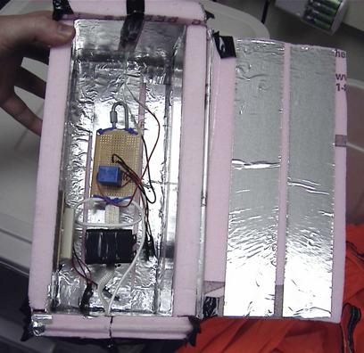
Figure 6.3.2: Actual Cut-Down System employed by BalloonSat
As seen above, the cut-down system, except the timed and DTMF circuits, are enclosed in an insulated box which is located above the parachute. This insulation ensures that, if any problems should occur, the heat from the NiCr wire will not damage any other component of the system unintentionally. The cut-down system weighs less than one pound making its impact on the mass of the entire system negligible. In addition, the light weight of the component prevents it from interfering with the parachute after once the balloon has been released.
In order to assure that the payload is returned safely to Earth so that the FASTRAC components can be retrieved unharmed, it is necessary to use a parachute to slow its descent.
In addition to researching balloons, the students in the fall of 2003 also researched parachutes for the mission. They determined that the descent rate can be determined by
the relation
|
|
|
2 |
where W is the combined weight of the payload and parachute, S is the surface area of the parachute, and ρair and Cd have the same meaning as in Equation 1.
In selecting a parachute vendor, EOSS was once again contacted for their advice and a company named Spherachutes [SPHEREACHUTES] was suggested. Spherachutes offers a 120”, 1.19lb parachute, at a cost of $130, which is capable of delivering a payload of 21-37lbs back to Earth at a rate of descent between 15-20 ft/s. This parachute, along with all the other Spherachutes parachutes, is constructed of 1.9oz coated rip-stop nylon, which is a material that prevents a rip from propagating if a rip were to form in the parachute [SPHEREACHUTES].
As with the balloon theory, the parachute theory was abandoned in favor of EOSS’s previous, practical experience. EOSS suggested that, to determine which parachute to use, simply determined the mass of the payload and beacon and look up which parachute to use in Spherachutes payload mass tables. This was the procedure followed to determine that the 120” parachute would be the chute required for the BalloonSat mission and no calculations or analysis were necessary. The figure below is a photo of the parachute purchased from Spherachutes.
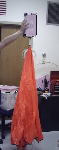
Figure 6.4.2.1: 120” Parachute Purchased from Spherachutes with Cut-Down System Attached.
The FAA, in addition to requiring two cut-down systems, requires that the balloon system be equipped with a radar reflective surface to allow all air traffic to monitor the location of the balloon [FAA Regulations]. In compliance with this regulation, a radar reflector, seen below, was purchased for approximately $30, which would give BalloonSat a radar signature similar to that of a small airplane.
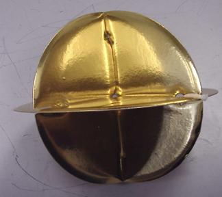
This particular radar reflector can be simply clipped onto the parachute lines, allowing for extremely quick attachment and detachment. The reflector is also made almost entirely of cardboard giving it a very small mass which means that its weight may be neglected in the overall mass model of BalloonSat.
At the extremely high altitudes which the BalloonSat will begin its descent, the air is very thin. While traveling through such a low density of air, the parachute will have difficulty staying open. To keep the parachute open during its descent, a ring has been attached to the parachute lines approximately 4’ below the parachute canopy. This ring, which is in actuality just a hoola-hoop purchased from a local toy store. The hoola-hoop was then zip tied to the each parachute line ensuring that the lines stay separated during the flight. The addition of the parachute ring not only ensures that the chute will stay open during its descent, the ring also ensures that the parachute lines will not become tangled, preventing the chute from opening far enough to provide the proper deceleration of the system. Below is a photo of the parachute ring after it has been zip tied the chute lines.
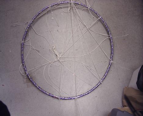
Figure 6.6.1: Parachute Ring Attached to Chute Lines.
Initially it was unclear how each of the components of the system, the balloon, parachute, payload, and beacon, will be connected to one another. The parachute would be connected to the cut-down system by the loop on the top of the chute, visible in Figure 6.6.1 above, but, as for the other components, further design work needed to be done.
Two ideas arose, as to how to connect the payload to the parachute. The first, seen below in Figure 6.7.1, is a soft, outer capsule which would house the payload. This capsule could then be hooked directly to the parachute tether by simple carabineers. This solution has been used by other balloon satellite groups, but it would be necessary to design and build the capsule itself which would require extra design and test time.
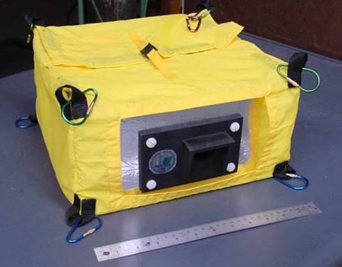
Figure 6.7.1: Possible Payload Capsule [Borealis]
Another idea for connecting the payload to the parachute tether, as seen in Figure 6.7.2 below, was to incorporate a hollow tube into the design of the outer shell of the payload itself. A parachute tether could then be run directly through the center of the payload. Knots in the tether would prevent the payload from traveling up or down the tether during the mission. This design would allow the payload the freedom to spin on the tether, thus reducing the stresses placed on the structure by the motion of the parachute.
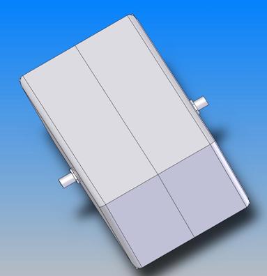
Figure 6.7.2: Parachute Mounting Rod
After consideration of each of the previous ideas, we decided to create capsules, or pouches, which would contain the payload and beacon respectively. This design has been proven effective by the BOREALIS group in Montana, who constructed the capsule seen in Figure 6.7.1. A design was finalized which called for the payload and beacon capsules to be constructed of rip-stop nylon with woven nylon straps which would run along the centerline of all sides of the pouches, excluding the top. These straps would also for the loops which would allow the capsules to be simply tied to each other and, subsequently, to the rest of the balloon unit. Luckily, a company named All-American Flags and Banners, in Austin, Texas, donated the rip-stop nylon needed to complete the design. The woven nylon straps were then purchased from a local fabric store. The rip-stop nylon was measured, cut, and sewn by Mecca Musick, to form boxes which allowed for ½’ of foam padding to be placed on all sides of the payload and beacon. The final pouches sewn for BalloonSat can be seen in following two figures.
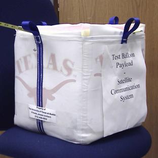
Figure 6.7.3: Completed Payload Capsule
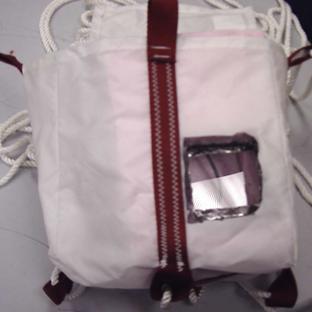
Figure 6.7.4: Completed Beacon Capsule
As seen above, pouches may be connected by threading ropes between the nylon loops on the respective capsules and tying the capsules to one another and the rest of the balloon unit. The rope used to accomplish this was a nylon rope with 120lb working load limit. 100’ of this rope was purchased from a hardware store, but since the entire BalloonSat system was approximately 30’ in length, not all 100’ were needed.
In order to assure the recovery of the FASTRAC payload, a tracking beacon was developed to be a redundant system to the FASTRAC equipment in the payload. This will enable us to track the payload in a mobile unit after the WRW station loses track of it near the ground outside the line-of-sight. The beacon will use the Global Positioning System to determine the payload’s longitude and latitude. The data will then be sent to a terminal node controller to change the digital data to an analog signal. This will then be transmitted out to the mobile ground station through a transceiver. The tracking beacon is based on the Edge of Space Sciences (EOSS) MicroAPRS system as seen in Figure 6.8.1 [EOSS]. This beacon model was chosen since it is small, lightweight and economical.
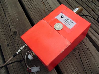
Figure 6.8.1: EOSS MicroAPRS System [EOSS]
The following information in the next two sections was obtained through Dr. Lightsey’s Satellite Navigation class [Lightsey]. The Global Positioning System (GPS) was developed jointly between the US Navy and the Air Force starting in the late 1960s. The idea behind the system was to enable the U.S. military to make accurate estimates of position, velocity and time. GPS was declared operational in 1995 and shortly after was approved for civilian use. Many features integrated into the GPS architecture enable the system to function with the success and reliability it does today. First, GPS was chosen to be a passive system. A passive system constantly broadcasts information and a user simply turns on the equipment to receive data. While an active system needs the user’s equipment to interact with the system. The passive system allows an infinite number of users access to the system at any given time, while the active system could only handle a predetermined maximum number of users. Since the active system needs interaction this would put military users in danger since their positions could be found due to the radiating signals to the system. With the passive system the signals sent out must be low power. Since the system sends continually, a high power system would interfere with virtually all electronic system. Thus the GPS signal’s power spectrum stays below the electronic noise level, thereby eliminating interference due to the system. Another problem was how to broadcast the signal. One way to accomplish this would have been to give each satellite its own frequency. However this would have complicated receiver design and increase the time to position fix. The receivers would need an adjustable antenna to be able to pick up all satellites. To circumvent this problem the system was designed as a Code Division Multiple Access (CDMA). CDMA is a technique for modulating multiple channels, in this case each satellite, on the same frequency at the same time. Each of the satellites is given a piece of a master code and is broadcast out on the same frequency. The GPS receiver compares the incoming signals and determines which satellite is being received. The position fix method used is trilateration.
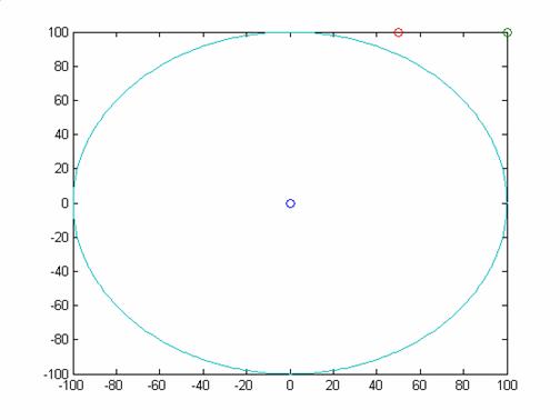
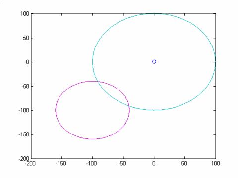
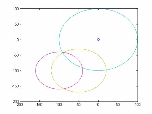
Trilateration is achieved by calculating the time of arrival of multiple signals. In order to achieve a fix, first assume that there are 3 stations at known locations (X1,Y1), (X2,Y2) and (X3,Y3). Also assume that that all clocks are perfectly synchronized (i.e. each station and the receiver clock). Assume the stations all emit a radio wave at a synchronized time, and the user times each of these signals. Using the speed of propagation of radio waves, 3*108 Km/s we can find the range from each station. We need all three stations to get an absolute 2D solution. If for instance we only have 1 station, only one range is known. The best we can do is know that we are within a certain range of that station. This can be seen in figure 6.8.2.1, the user can be anywhere on the circle surrounding the station. With 2 stations we receive a better solution, figure 6.8.2.2. The user must lie at either intersection of the 2 range circles surrounding the stations. Knowing an apriori position we can deduce the likely position. With all three there is one unique solution as seen by the intersection of all three circles in figure 6.8.2.3. This is analogous to the GPS Position fix except that in 3D the circles change into spheres. Also, the satellites clocks are almost perfect but the user clock is not this means that we need an extra satellite to obtain the amount the user clock is offset from GPS system time. Four satellites are required to make a position fix. Using 4 satellites is similar to the 2 station example in 2D. We have 2 position solutions, and fortunately one occurs on Earth’s surface and the other occurs in space so in most applications we know the user is on Earth’s surface so that is the position that is reported.
|
|
Figure 6.8.2.1: Positions with only 1 Station
|
|
Figure 6.8.2.2: Positions with only 2 Stations
|
|
Figure 6.8.2.3: Final Position Solution with 3 Stations
Automatic Position Reporting System (APRS) was designed by Bob Bruninga starting in the early 1990’s. The system allows uses to exchange their location with others automatically via radio. APRS is different than Packet Radio, which once was the default protocol to send information via Armature Radios; APRS turns packet radio into a real-time tactical communications and display system for position information using maps. APRS uses a GPS receiver to input data into a terminal node controller than out through a radio. This is the system we will use to obtain the location of the payload over the entire flight.
The tracking beacon is a separate system from the FASTRAC payload; this ensures total redundancy of the position information and ensures payload recovery. The main structural component of the cases is an aluminum chassis box. The dimensions of the box are 8x6x3.5 inches. This gives the beacon a lightweight but strong structure. The main drawback to aluminum is its good thermal transmissibility properties. At the altitude we will be flying at the temperature is -100ºC. Thus insulation will be needed in and around the box. For the insulation it was decided that we use the same Fomular insulation discussed above. A heater was also added to increase the internal temperature. This heater was borrowed from the SHOT workshop payload. With the heater and the insulation the beacon is able to keep all the electronics within their operating temperature.
The GPS receiver is the actual component that receives the GPS signal and makes the positioning measurements. It is the base of the tracking beacon. In order to choose the best GPS receiver for our mission we defined a set a requirements. First, the receiver must be light weight and have small dimensions, so the beacon would be negligible in comparison to the payload. The receiver needs to run on minimal power. This will maximize the useful running time of the batteries. Batteries weigh considerably more than electronic components; thus minimizing the battery consumption will allow the beacon to be lighter. Second, one of the most important requirements is that the receiver must be able to position fix above 100, 000 feet, our target altitude. Losing the balloon at any altitude would prove detrimental to recovery since we may never regain contact with the balloon. After September 11, 2001 the Department of Defense (DOD) limited commercial receivers to an altitude of 60,000 ft if the velocity of the receiver was greater than 1000 knots. The DOD enacted this legislation to keep GPS receivers from being added to bombs for guidance. Since our balloon will not be traveling greater 1000 knots the altitude limit will not hinder our flight. If we were to travel faster we would have to obtain a license under the International Traffic in Arms Regulations from the government
Third, the output protocol needed from the receiver must be in NMEA format. Finally, the receiver must be able to stand extreme temperatures and be robust.
The first receiver we considered was the Garmin Etrex, which satisfied many of our requirements. First it is known to work at altitudes greater than 100,000 feet. The actual receiver is one of the smallest and lightest handheld models. Also, the internal components of the receiver are well documented by third party sources. The receiver is also very economical. However, we would need to disassemble the receiver so it could be connected to the terminal node controller. The Etrex only has the capability for an internal antenna, but we need an external antenna since the receiver will be mounted in the beacon.
For the second receiver we decided to stay with Garmin since the Etrex fit many of our requirements. We chose the Garmin 25. This is the GPS engine that all of Garmin’s products use. The Garmin 25 only contains the necessary components to make the positron fix. This will solve the disassembly problems of the Etrex receiver. The Garmin 25 also has the height and power capabilities of the Etrex. Plus it has the capability of using an external antenna. The main problem with this receiver is that with the external antenna it is more than twice as expensive as the Etrex.
The GPS receiver that we eventually chose was the Motorola Oncore M12+, seen in figure 6.8.5.1 The M12+ like the Garmin 25 is a GPS engine only, so we would not have to do major modifications to the receiver. As with both the Garmin’s the M12+ will position fix at altitudes above 100,000 feet. It is also the lightest and smallest of the three receivers that we looked at. The M12+ utilizes an external antenna. Earlier versions of the Oncore receiver family have been utilized by the department’s CanSat program. The M12+ was the most economical of the 3 receivers at $111.70 for the receiver and its antenna.
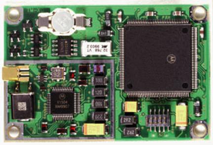
Figure 6.8.5.1: Motorola Oncore M12+ GPS Receiver [Motorola]
Terminal Node Controllers (TNCs) are used to translate digital data to analog data and vice versa. This is an important step in the transmitting of data to the ground station and the receiving of commands at the payload. Our requirements for the TNC are it should be able to read in NMEA data and change it to a VHF signal. The TNC, similar to the GPS receiver, must be able withstand extreme environments and to be light weight, small in size, and operate at a low power.
We first considered a Kantronics TNC similar to the one utilized in the FASTRAC payload. The Kantronics has been proven successful on satellites, and the FASTRAC Payload, and it is also used at the WRW Tracking Station. This would provide the beacon with a powerful TNC. However, we do not need the full capabilities of the Kantronics. Also, the size and weight are much larger than what is useful for the beacon. The Kantronics is overkill for our purposes.
After researching other high altitude balloon programs such as EOSS and BOREALIS we found the TinyTrak3, as seen in figure 6.8.6.1 with a quarter for scale. The TinyTrak3 was designed by Byon Garrabrant. It is a GPS position encoder instead of a full TNC. It takes GPS code in NMEA code and outputs it in APRS protocol. The TinyTrak3 is the smallest and lightest weight TNC available for GPS position reporting. The TinyTrak3 uses resistors to modulate the position data onto an analog carrier, this means that it is less efficient at converting data than the Kantronics but not enough to warrant using the Kantronics. Also, the TinyTrak3 is often used in high altitude ballooning. This is the TNC we chose for the beacon. Fully built we obtained the TinyTrak3 for $65.
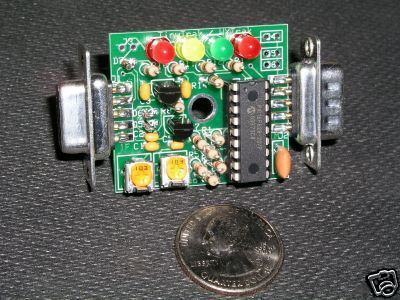
Figure 6.8.6.1: TinyTrak3 with quarter for scale [Byonics]
Transceivers are the actual radios that send and receive data. This like all other components of the beacon needed to work at low power, be light weight and have small dimensions. Therefore we chose the Alinco DJ-C5T. This is the smallest commercially available transceiver available. It can be reduced to a size similar to the Motorola Oncore M12+.
We choose to fly a camera to take pictures during the flight. The idea was a result of the SHOT workshop. Part of the payload that was flown was an Olympus 35mm camera. This enabled the team to take 36 pictures during the flight. However due to the limited number of pictures only a handful were of good quality. Due to this we decided to fly a digital camera so we would be able to take many more pictures. We choose to look for a 3 mega pixel camera to maximize the picture quality while still having a low file size. The camera we choose was the Camera Concord Eye-Q 3340z. The camera resolution is 3.1 mega pixels; it is also small 2.87 x 1.42 x .75 inches and weighs .46 lbs with batteries. It also has a media expansion slot which enabled us to increase the amount of pictures we can take. The camera at full quality will store 15 images using 16 megabytes of memory. We added a 256 Megabyte card which brings our total number of pictures available to 240 or approximately 1 every 30 seconds. The way pictures are taken in this digital camera is that when the button is pressed it completes a circuit and sends a pulse telling the camera to take a picture. In order to automate the picture taking we first had to find the capacitor and bypass it. This proved harder than it should be the capacitor was buried deep in the structure of the camera. With a little patience it was found. We then connected leads to both the positive and negative sides and tested the camera again. It took a picture every time the leads were connected. To take the pictures in intervals we utilized the camera circuit from the SHOT Workshop as seen in Figure 6.8.8.1. The camera circuit is based on the 555 Timer Integrated Circuit. The 555 is the “first and only commercially available timer integrated circuit available” [555 TimerTutorial]. The circuit operates by sending a pulse of voltage at regular intervals based on the potentiometer settings. During the SHOT Workshop it was configured to trigger every 3 minutes since they were only able to take 36 pictures. After adjusting the potentiometers we were able to reduce that to 2 minutes which was still to large for our requirement of 1 every 30 seconds. After consulting the SHOT Manual we were able to track down the resistor at point A in Figure 6.8.8.1, which was responsible for giving the circuit such a long period. To reduce the period further we needed to reduce the resistance at that place in the circuit. We did this by piggybacking another much smaller resistor in parallel thus reducing the equivalent resistance of that position. The final pause interval was 35 seconds which was close enough for our purposes.
![]()

Figure 6.8.8.1: Camera Timing Circuit
As mentioned earlier the FAA requires that any unmanned balloon must be equipped with two independent payload cut-down systems [FAA Regulations]. For our flight we choose a Digital Tone Multi Frequency DTMF decoder and a Timer. To create the DTMF decoder circuit we first programmed a microprocessor which would compare the codes coming from the DTMF Decoder to the preprogrammed one which would initiate the cut down. The code we choose was a 3 tone code to reduce accidental cut down of the system due to outside users. The actual DTMF Decoder was then connected to the microprocessor. The Decoder extracts the code from the incoming voice string. To provide this voice string the Decoder was connected to our transceiver. In order to trigger the cut down we first would send the code over our ground radio, which would be received at the beacon’s transceiver. This audio would then be sent to the DTMF Decoder which would assign the appropriate code to incoming audio. This code would then be compared to the code on the microprocessor and if it matched a cut down pulse would be sent up to the actual cut down circuit and the wire would be burned. We also incorporated a timer into the microprocessor by having it listen for the DTMF command for 2.5 hours. If the command had not been received in the time period the cut down would be automatically triggered. The time limit was chosen to add an hour of time to our flight time to ensure we had extra time to adjust the system if necessary.
 The first step in
building the beacon was to provide power to the TinyTrack3 (TT3). This was
achieved by providing 9 Volts via the J3 connection on the board as seen in
figure 6.8.10.1. After the TT3 had power we were able to configure it. The TT3
has a DB-9 connector on either side of it. Configuration was achieved by
connecting the male side to a computer through a null modem cable. A null modem
cable switches the second and third pins between the computer and the TT3. In
the configuration screen seen in figure 6.8.10.2 we adjusted it by using my Ham
Radio Call sign, we also told it to send data every 10 seconds.
The first step in
building the beacon was to provide power to the TinyTrack3 (TT3). This was
achieved by providing 9 Volts via the J3 connection on the board as seen in
figure 6.8.10.1. After the TT3 had power we were able to configure it. The TT3
has a DB-9 connector on either side of it. Configuration was achieved by
connecting the male side to a computer through a null modem cable. A null modem
cable switches the second and third pins between the computer and the TT3. In
the configuration screen seen in figure 6.8.10.2 we adjusted it by using my Ham
Radio Call sign, we also told it to send data every 10 seconds.
![]()

Figure 6.8.10.1: Tiny Track 3 Board

Figure 6.8.10.2:Tiny Track 3 Configuration Screen
After configuring the TT3 we were able to connect the radio and the GPS receiver to the TT3. To connect the radio to the TT3 an audio adapter was made to fit in the Alinco’s microphone input port so we could access the microphone input, speaker output and the microphone/speaker ground. The configuration for this connector can be seen in figure 6.8.10.3.

Figure 6.8.10.3: Alinco Mic/Earphone Configuration
A female DB-9 was attached to this connector. The microphone wire was connected to pin 1, the speaker was connected to pin 5 and the radio ground was connected to pin 6. Power was obtained for the radio through the TT3 to do this a connection was made from the radio voltage in to pin 7 of the female connector. This connector was then zip tied to the male connector of the TT3. Next the GPS receiver was connected to the TT3. To do this we used the Motorola Evaluation Board this enabled a direct connection to the TT3. Power was applied through the same 9 volt source the TT3 was on. Power for the DTMF Decoder circuit was also obtained through the TT3 by a parallel connection at the radio’s power input. Additionally the camera was connected to it timer circuit. To allow the camera to see out a hole was made in the box and covered in plexiglass. Also a hole was cut to allow the antenna to hang beneath the beacon. Another hole was cut to allow the wire to extend to the cut down circuit above the parachute. Before the electronics were added a layer of Foamular was epoxyed to the interior walls. Then the electronics were then fit and epoxyed into position. On launch day the final exterior layer of foam was epoxyed to the outside of the beacon, which was then placed in its pouch and it was ready for launch. Now that each component of the balloon unit has been designed, constructed, and connected to each other and the payload, the time had arrived to design the mission itself.
 |
|