The payload consists of 4 major parts: FASTRAC components, aluminum structure, the insulating foam, and the heater.
Our previous design called for outer shells, 4x6x12 in. aluminum boxes, available from the physics store, that have one large face open and would be latched together to form a shell. Figure 5.0.1 shows how the substructure and components fit inside half the outer shell. Note, insulation is not shown for clarity.
Figure 5.1.1: Substructure inside half the outer shell.
Figure 5.2.1 shows the first basic aluminum structure considered. The substructure shown in Figure 5.2.1 is made up of a flat plate base with L-bars along the perimeter allowing other L-bars to stand upright. The standing L-bars are versatile allowing them to be spaced to fit any electronics cards between them with the use of card guides, in addition to contributing structural strength. Card guides are pieces of plastic which allow electronic components to slide in and out of the slots with ease.
When it is all put together, it looks something like Figure 5.2.2.
Figure 5.2.2: Payload construction with base, perimeter L-bar, standing L-bars and top.
The cross members ensure that the box does not deform into a rhombus under shear stresses. The mass of the substructure is 575 grams.
After some deliberation, we determined this structure had too many components and that would make it hard to fit them all together. FASTRAC had encountered the same problem with a previous project, CanSat. CanSat had too many components with tight tolerances and did not fit together well. Therefore, to reduce the number of elements, we decided to go with this next structure shown in Figure 5.1.3.
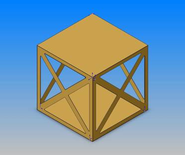
Figure 5.2.3: The 2nd payload iteration.
This design reduced the number of members significantly but still had very small tolerances that left no room for error if it was to fit together properly.
Additionally, we created cardboard mock ups of the components and tried to fit them all in the 4x6x12 in. aluminum boxes available from the physics store. Although the Kantronics modem mock up fit, when the actual component, with connectors, was fit checked, it was too large. The design with clam shells was scrapped at this point.
So starting from square one, we thought the simplest structure to construct would be a cube made from aluminum sheets. The top would be removable for access to the parts and the sides would be attached to the bottom either by fastening them to L-brackets or creating tabs in the bottom and bending them to create the ‘L’. After consulting Rick Moldando, one of the machinists for the aerospace department, on bending aluminum, the tabbed-bottom design was chosen as the aluminum we were using was thin enough to take the perpendicular bend.
The new box was going to be 9x9x9 in. That makes it tall enough for the largest component, the Kantronics with connectors, and its sides are all the same size because this would be easier to manufacture. We scavenged some .08 in. (2 mm) thick aluminum plates from old computer cases found in the elevator storage room of WRW.
This final iteration seemed like the most feasible, robust, and least expensive payload design. Early stages of its construction are shown in Figure 5.1.4
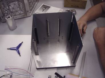
Figure 5.2.4: The final iteration of the payload in the early stages of construction.
Notice, we still employed the L-brackets to hold the card guides on the side of the structure to secure all the electronic components. The battery holders were fastened to the bottom of the box at this point. This was done because the batteries are the heaviest component and we needed the center of mass and the center of pressure, the middle on a flat plate, to coincide so that the box does not have a pitching moment during its free fall. An off center pitching moment would cause unwanted payload tumbling. Also, assuming that the payload will impact the ground with the bottom first, the safest place for the batteries is the bottom so that they do not shake loose and hit any of the other electronic components.
The box was sealed with silicon adhesive along its seams and fastened together except for the top.
The initial insulation design consisted of two parts, FoamCore and housing insulation. FoamCore board feels a lot like cardboard but looks white and contains, as the name states, foam in the middle. This was to be placed around the aluminum substructure to create a barrier between the other insulation and the electronic components so that particles do not get on the electronics. The other insulation would have done the majority of the insulation as well as absorb shock upon impact. This design was scrapped because first, we are no longer using an aluminum substructure with an outer shell and secondly, the spray foam was speculated to contain air bubbles that would burst at low pressures that it will encounter at high altitudes.
The new design used ¾” Foamular, extruded polystyrene, which is used in building construction, to cover the sides. This material was chosen because it is a good insulator, light, and workable. A picture of the insulation attached to the payload can be seen in Figure 5.2.1.
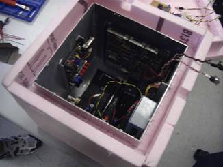
Figure 5.2.1: Payload covered with ¾” Foamular insulation.
There is a double sheet of insulation to help keep it better insulated. At each seam in the insulation, silicon adhesive is applied to make the payload as air tight as possible; the sheets are held together with epoxy.
The Foamular we chose has an R-value of 4 with a compressive strength of 25 psi [PINK, Under Slab]. To calculate the impact resistance, we multiply the impact surface area by 25 psi (172,368.932 N/ m2). The bottom piece of insulation is a 12x12 in. square, so the surface area is 144 in2 (0.092903 m2). So the force it can handle is 3600 lbs (16013.59 N). Using Newton’s first law,
![]()
and an overestimated mass of the payload, 20 lbs (9.0718474 kilograms), the impact acceleration would be 5,791.3 ft/s2 (1765.2 m/s2) or roughly 180 g’s. This shows that the payload would have to be accelerating 180 times the acceleration here on Earth to reach the compressive strength of the insulation. The 25 psi shows us that the insulation will be durable enough to sustain a landing. Even if some insulation is destroyed, it is not a big loss because it is inexpensive and can easily be replaced for subsequent missions.
Using this R-value, the dimensions of the payload, a temperature distribution of the atmosphere, and the conduction heat equation, the average heat loss was calculated to be about 17 Watts. The MATLAB files for the thermal model are shown in Appendix A.
The BalloonSat heater is based on a previous design by the EOSS group in Colorado. EOSS has flown these heaters in small payloads built by students attending a balloon building workshop (SHOT) during the summer of 2003. EOSS considered using chemically activated exothermic hand warmers, but at high altitudes and low air densities, there is not enough oxygen to work. They used active electric heaters that consist of three 4 ohm sand resistors in series, for a total of 12 ohms, powered by a 9V battery. The SHOT payloads were small and not very well insulated; they reached temperatures of -20 °C.
The goal of the heaters for BalloonSat would be to keep the inside temperature above 10 °C to keep within operating temperatures of the electronics. The critical temperature is around -10 °C because that is when batteries stop working. For this we used three 10 ohm wire wound resistors in parallel. These wire wound resistors have a 10 Watt power rating, and careful attention was paid to get the resistors close but not over 10 watts as to not burn them up. The resistor/battery combinations were worked up in an Excel spreadsheet shown in Appendix B. Using 9 volts and 3 resistors in parallel, the total resistance would be 3.3 ohms with a current draw of 2.7 amps. At a high current draw, the batteries will produce useful additional heat. The power drained by the circuit is 24.3 Watts, higher than the 17 Watts of heat power needed. Heat power and electrical power do not correlate one to one exactly, but it is a good indication that this is on the right track. The resistor pack was tested with three 9 Volt batteries in parallel and the batteries were drained after half an hour. If the flight was to last 1.5 hours, the batteries would have to last three times as long. The final heater design has nine 9 volt batteries in parallel with three 10 ohm resistors. The schematic is shown bellow in Figure 5.4.1 and the resistor pack is shown in Figure 5.4.2.
Figure 5.4.1: Schematic of the heater used in the payload.
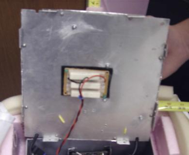
Figure 5.4.2: The resistor pack attached to the top of the payload.
The payload needs to be put through two tests, a structure and thermal test, to make sure it will be able to meet the BalloonSat requirements. The first test was based on the testing done by SHOT detailed in the SHOT workshop manual [SHOT Workshop]. SHOT suggests you roll the payload down a flight of stairs to simulate the impact and subsequent tumbling of the landing. This test was carried out without the components to make sure they did not break, but the structure survived and passed the test. The thermal test consists of putting the payload in an ice cooler with some dry ice. Dry ice (CO2), has a temperature of about -80 °C. This is pretty close to the temperature that will be encountered. The temperature inside and outside the payload will be measured and the heater will be turned on. Once it has sustained two hours of sub-zero temperatures, the temperature data recorded will be analyzed to make sure the apparatus does not have an inside temperature that would be dangerous for operation. This would be around -10 °C, where batteries begin to freeze and become non-functional. This test was not carried out because during the week before launch, there was a big crunch on finishing other, more important components that are necessary for BalloonSat’s function. The decision made by FASTRAC management was that the heaters provided would be sufficient enough to keep BalloonSat warm long enough to get data to prove that it would function and that it would only be non-functioning for a small duration. It would begin to work again when the payload descended and warmed up.
The communications components consist of the Kantronics KPC-9612 UHF/VHF Modem shown in Figure 5.6.1 and the radio receiver and transmitter. The modem will translate radio signals, sent by the satellite tracking station, into binary code for the microcontroller.
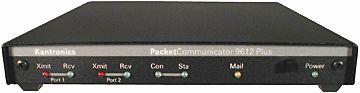
Figure 5.6.1: Kantronics UHF/VHF Modem
The receiver/transmitter duo will be the Hamtronics R-100 VHF FM Receiver and the Hamtronics TA451 UHF transmitter seen in figures 5.6.2 and 5.6.3 respectively. This will be how FASTRAC and BalloonSat communicate with the ground station sending data over the radio waves at frequencies of 144-146 MHz and 435-438 MHz respectively.
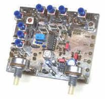
Figure 5.6.2: Hamtronics R-100 VHF FM Receiver.
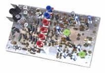
Figure 5.6.3. Hamtronics TA451 UHF Transmitter.
The GPS receivers are modified Mytel Architect GPS receivers. DLR, the German space agency and a post-doc student at the University of Texas made modifications to make them space ready and are now called Orion GPS receivers. They are shown in Figure 5.7.1. The receivers will gather data from GPS satellites about position and velocity and send the data on to the modem to be sent back down to the ground station and the second FASTRAC satellite.
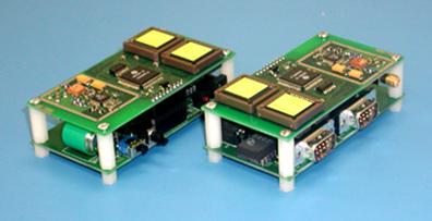
Figure 5.7.1: FASTRAC GPS Receivers
 |
|
