Appendix A
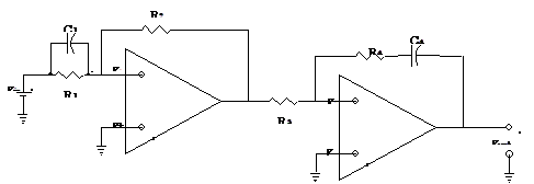
Electrical Circuit Schematic of Educational Servo System

Appendix B
Important Laplace Transform Pairs [19]

Appendix C
Data from Process Dynamics Modeling Experiment

Appendix D
This section provides several types of analog controllers and derivations of their
transfer functions.
transfer functions.
Proportional Controller
The proportional controller, commonly referred to as a P controller, provides the
transfer function of the from listed below
transfer function of the from listed below
 [D.1]
[D.1]
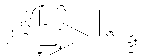
The proportional controller is the simplest type of controller; its transfer function may be
implemented with the op amp circuit shown in figure 51 below
implemented with the op amp circuit shown in figure 51 below

Assume that the input voltage, Vin, is representative of the error between the input
reference value and the actual value. Analysis of the circuit in figure 51 is similar to the
inverting amplifier analysis from Section 6.3. It is left as an exercise to the reader to show
that the transfer function between in the input voltage and the output voltage, Vout, is as
follows
reference value and the actual value. Analysis of the circuit in figure 51 is similar to the
inverting amplifier analysis from Section 6.3. It is left as an exercise to the reader to show
that the transfer function between in the input voltage and the output voltage, Vout, is as
follows
 [D.2]
[D.2]
As shown in equation D.2, the ratio of the resistors provides the gain of the controller. If the
negative sign in the transfer function is not desired an inverting amplifier may be utilized.
negative sign in the transfer function is not desired an inverting amplifier may be utilized.
Proportional-Derivative Controller
The proportional-derivative controller is commonly referred to as the PD controller. A PD
controller provides a transfer function of the form below
controller provides a transfer function of the form below
 [D.3]
[D.3]
The transfer function of a PD controller may be implemented with the circuit shown below
in figure 52.
in figure 52.

Let the input voltage, Vin, be representative of the error between the desired value and the
actual value. Recall the relationship between the current through a capacitor and the
resulting voltage across the capacitor is given be the following equation
actual value. Recall the relationship between the current through a capacitor and the
resulting voltage across the capacitor is given be the following equation
 [D.4]
[D.4]
Using node voltage analysis we can write an equation summing the currents at node b
 [D.5]
[D.5]
Recall from section 6.3 that the voltage at the negative input terminal to the op amp is
approximately zero if the positive terminal is grounded. Equation D.5 may be simplified as
follows
approximately zero if the positive terminal is grounded. Equation D.5 may be simplified as
follows
 [D.6]
[D.6]
Furthermore, because v- 0, the sum of the voltages from the input voltage to the voltage
across the capacitor equals zero
across the capacitor equals zero
 [D.7]
[D.7]
Combining equations D.6 and D.7 yield a differential equation relating the input voltage to
the output voltage
the output voltage
 [D.8]
[D.8]
Applying the Laplacean operator to equation D.8 and simplifying yields a transfer function of
the form in equation D.3
the form in equation D.3
 [D.9]
[D.9] [D.10]
Proportional-Integrating Controller
The proportional-integrating controller is commonly referred to as the PI controller. A
PI controller provides a transfer function of the form below:
PI controller provides a transfer function of the form below:
 [D.11]
The transfer function of a PI controller may be implemented with the circuit shown below in
figure 53.
figure 53.

For the same reason as in section 6.3, v- 0. Because the input voltage at the negative
terminal of the op amp is approximately zero, the sum of the voltages across R2, the
capacitor, and the output voltage is zero. Furthermore, iin is the same current that passes
through R1, R2, and C
terminal of the op amp is approximately zero, the sum of the voltages across R2, the
capacitor, and the output voltage is zero. Furthermore, iin is the same current that passes
through R1, R2, and C
 [D.12]
Taking the derivative of equation D.12 yields the following result:
 [D.13]
Equation D.13 may be combined with the defining equation of a capacitor, as shown in
equation D.4. The result is a differential equation relating the input voltage and the output
voltage
equation D.4. The result is a differential equation relating the input voltage and the output
voltage
 [D.14]
Once again the Laplace operator is applied to the differential equation. The simplified from
of the transfer function between the input and output voltage resembles the form in
equation [D.11]
of the transfer function between the input and output voltage resembles the form in
equation [D.11]
 [D.15]
 [D.16]
Proportional-Integrating-Derivative Controller
A proportional-integrating-derivative controller is typically called a PID controller. The
defining transfer function of a PID controller is of the form presented below
defining transfer function of a PID controller is of the form presented below
 [D.17]
transfer functions of a PI and a PD controller. First start with the transfer function of the
PD controller on the left
 [D.18]
 [D.19]
Further the transfer function may be shown to be of the form in Equation D.17:
 [D.20]
|
|

