Satellite
Tracking Station Motion Control

Team
Members:
Anne Burnham, Marcin Lenart, Christopher Velez,
David Weyburn
Advisors: Dr. Ronald Stearman,
Thomas Campbell
May
7, 2003
Aerospace Engineering
and Engineering Mechanics Department
The
University of
Texas at Austin
Go to Table of Contents next>
Errata
-
Section three has been
deleted from the final report; hence, section two leads directly into section
four.
-
All references to the
PXI-7734 should instead be references to the PXI-7344.
Abstract
At
the beginning of the semester, the tracking station, which was acquired from
the U.S. Air Force in 2002, was only capable of manual motion-control from the
roof of W. R. Woolrich (WRW) Laboratories.
Remote control of the dish from the Satellite Design Laboratory (SDL) is
necessary for the station’s future application in the Formation Autonomy
Spacecraft with Thrust, Relnav, Attitude, and
Crosslink (FASTRAC) program. The goals
of this project were to design and implement dish motion sensor arrays and to
create an application for manual and automated dish control. The two sensor arrays contain three
magneto-resistive sensors. One array
monitors horizontal motion of the dish, and the other monitors vertical motion
to prevent over-rotating and damaging the wires. The user interfaces with the application
through a Graphical User Interface (GUI).
Manual Control, Go-To, and Follow functions of the motion-control
application implement user inputs to command the motor to move to a specified
location and to follow a specified path.
The team completed the sensor array design and tested a sensor circuit.
Manual control and Go-To functions were also written, and limited software
control of the dish has been achieved.
LiNC determined that the dish motors do not output an index pulse as
required by the National Instruments (NI) Motion Controller. As a result, the software could not be used
to control the dish for more than 5 seconds at a time. Future design groups may attempt to
manipulate the pulse-encoded output of the motor to locate or emulate an index
pulse or abandon the controllers entirely. Once extended remote control is
obtained, the Follow function is written, and the sensor arrays are installed,
satellite tracking can take place.
Acknowledgements
LiNC would like to thank Dr. Ronald
Stearman for giving us the opportunity to work on this design project. We would also like to thank Tom Campbell and
Dr. Glenn Lightsey for their help in completing the task set before us. Of course, without the overly generous support
of the US Air Force and National Instruments, none of this would be
possible. Thanks also to Honeywell for
their contribution and to the UT Aerospace Department’s Rube Goldberg team for
its tacit agreement to let us use some of their equipment.
<previous Go
to Table of Contents next>
In
2002, Dr. Glenn Lightsey, associate professor in the Department of Aerospace
Engineering at the University of
Texas,
established the Satellite Design Lab (SDL).
Housed on the fourth floor of the W.R. Woolrich Laboratories of the UT
campus, the SDL was established with “the goal of inspiring students in science
and technology through hands-on participation in actual space projects”
[Lightsey]. The SDL was intended to track and communicate with satellites and
to provide an area for the development and construction of satellites and
satellite components. In late 2002
construction began on the UT Satellite Tracking Station.
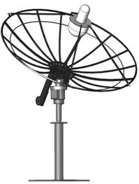
The antenna measures about 80 inches in height from the
ground plate to the bottom of the parabolic dish. The satellite dish measures 60 inches in
radius and 20 inches in depth. LiNC estimates the
focal length of the dish to be 43.6 inches.
A 4 amp fuse box is located on the side of the motor casing. There is another fuse inside the antenna box
in the lower right hand corner of the wiring casing.
Wiring to the satellite dish restricts the rotation about
the azimuthal axis of the satellite dish. The motion is restricted to 360° by
an aluminum stop. Structural constraints restricted elevation to 0° - 90°. See
Figure 1 for locations of the pertinent antenna features.
The
total height of the satellite dish in the stowed position is 161 inches, or 13
feet and 7 inches. The stowed position has the bowl of the dish facing straight
up. The height from the ground plate to
the motor mount is 78 inches, or 6 feet and 6 inches. The radius of the
satellite dish is 60 inches. The depth of the satellite dish is 20 inches.
Upon the
inception of the Tracking Station, the US Air Force made a donation. Included in the donation were two high-gain Yagi antennae and one 3 meter parabolic satellite
dish. Each antenna would be used for
various missions of differing natures.
Also included were independent positioning units for the antennae. The
dish and the Yagis required assembly and installation on the roof of WRW. Graduate student Thomas Campbell headed the
installation process. The Yagi antennae
were mounted on the roof and integrated with computers and a radio in the
Satellite Design Lab by way of conduits leading from the roof to the Satellite
Design Lab (SDL). The Yagis are already capable of automated control and are
able to track satellites operating on VHF and UHF frequencies. Some of the satellites already tracked with
the Yagi antennae include amateur radio satellites.
Currently,
operation of the satellite dish motors is only possible through manual control,
which is accomplished with a switch designed and built by Mr. Campbell. The switch interfaces directly with the drive
motors by way of a nine-pin connector.
Unfortunately, this interface is on the roof of WRW and requires a
person to be stationed there for the duration of operation. Such a restriction makes it impossible for
one person to control both the radios and the satellite dish. Furthermore, for a satellite to be tracked
one would have to be constantly using the manual control. Such actions would required
the operator to have precise and detailed knowledge of the satellite
trajectory. Not one of these
requirements is practical and for all intents and purposes, impossible.
The
Satellite Tracking Station will not only be used by aerospace students, but
also by the aerospace department in projects such as Formation Autonomy
Spacecraft with Thrust, Relnav, Attitude, and Crosslink (FASTRAC) and Remote
Accessible Communications Environment (RACE).
FASTRAC is a departmental satellite design project in which
nanosatellites are designed and constructed as part of a nationwide collegiate
program sponsored by the Air Force. The
Air Force has given 12 colleges, including The University of Texas at
Austin, a
two-year grant to build two flight-ready satellites that will demonstrate
technologies to be applied in formation space maneuvers. Aerospace companies and the United
States government have been exploring
the potential of using numerous smaller satellites flying in formation in lieu
of larger, more costly satellites in future missions. The benefit of using smaller satellites
flying in formation is that the smaller satellites are expendable. That is, it is easier to replace a small
piece of a satellite array than it is to replace an entire system. The Tracking Station will be instrumental in
testing for FASTRAC and in communicating with the satellites after their
launch. RACE is a program in which the
UT aerospace department hopes to one day participate. This program will allow control via the
internet of the UT Tracking Station and stations at participating
colleges. In addition to these programs,
general use by aerospace students will make the Satellite Tracking Station an
invaluable educational tool.
LiNC is
a four-member team comprised of aerospace engineering undergraduate
students. Each member brings to the
group diverse experiences and talents.
The team was split into two groups.
The first group worked primarily on the hardware for the project, while
the second group dealt primarily with the software development. While the members’ tasks were specific, they
are certainly not restrictive. The group
working on software was involved in the hardware development and vice
versa. Hardware development consisted of
researching, purchasing, fabricating, and installing any electronic or
mechanical parts. Team members working
on hardware were assigned acquire and install the sensor array and integrate
the sensors and satellite dish motor with the motion controller in the
SDL. Software development included
writing code to reposition the dish and evaluate algorithms for automated
satellite tracking. The members working
on hardware development were Anne Burnham and Christopher Velez. Marcin Lenart and Dave Weyburn worked on
software development. Figure 2 shows a
diagram of the team structure as it was defined at the beginning of the
semester.
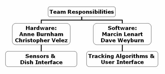
Figure 2. Team Structure
Diagram
<previous Go
to Table of Contents next>
LiNC’s goal was to automate the motion of the UT
Aerospace Department’s satellite dish. An overview of the architecture of the satellite dish
motion-control system is shown in Figure 3.
The user inputs a set of commands, e.g., “move to a particular point” or
“track this satellite across the sky”, into the computer via the graphical user
interface. The motion-control
application sends these commands to the
motion
controllers. Current is applied to the
satellite dish motors by the motion controllers, and the dish moves according
to user specifications. The motors and
the sensors installed on the dish give feedback, by way of the motion
controllers, to the motion-control application.
After the application makes the necessary calculations with this
feedback, the user is shown graphical information about the satellite dish’s
current configuration. With this
information, the user can make decisions about what next should be done with
the dish.
To
better facilitate the completion of the motion-control system, LiNC decided to develop four smaller goals. The smaller goals were intended to focus the
LiNC team on the specific needs of the hardware and software. The goals of the LiNC team were: to design
and implement a satellite dish mounted sensor array, connect the dish and
sensor array to the motion controllers located in the Satellite Design Lab,
create a motion-control application and graphical user interface, and choose
and employ an appropriate method for generating satellite ephemerides for use
in the automated tracking of satellites.
The satellite dish is capable of more than 370o
of azimuthal movement. More than 370o of movement, however, will
cause damage to the dish wiring. To
prevent damage to the wires, the satellite dish must not over-rotate. Aluminum
stops on the dish currently serve this purpose. At the beginning of the
semester LiNC aimed to replace these stops with two arrays of magnetic sensors
that would monitor the motion of the satellite dish and prevent over-rotation.
The
plan defined by the LiNC team at the beginning of the semester called for
sensors to act as cutoff switches on the parabolic dish. These sensors were to be placed strategically
on the satellite dish. The positions of
two sensors would be determined by evaluating the total possible rotation of
the dish and the total required/desired rotation of the satellite dish. A third sensor would be placed at a home or
default position on the dish. Once the sensors
were installed on the dish, their circuitry would be connected to the motion
controllers in the Satellite Design Lab.
LiNC also planned to develop sensor housing. As the satellite dish is on the roof, the
circuitry will be susceptible to the elements.
Housing will protect the sensors without interfering with their magnetic
properties.
The remainder of the concerns determined by the hardware
team at the beginning of the semester had to do with the satellite dish motors
and their connection to the motion controller in the SDL. The motors are pulse-encoded, which means
that as the motors drive the dish, they send a signal in the form of a square
wave. LiNC decided that the pulse-to-degree ratio
would be used in the determination of satellite dish position. For this to occur, the drive motors would
have to be connected to the SDL lab in much the same manner the sensor array
would be connected. The difference
between the two connections would be that the connection from the drive motors
to the lab would go directly from a junction box, whereas the sensor array
would need to connect to a separate junction box before going through the first
junction box.
Once the team had the wiring from the sensors and the
drive motors connected to the SDL, it would have to be connected to the
National Instruments PXI-7344 motion controller by way of the nine-pin
connector in the SDL.
In order to control the satellite dish from a computer in
the Satellite Design Lab, a motion-control application needs to be
designed. This application will consist
of two parts: the front-end graphical user interface and the back-end program
that runs the show.
A graphical user interface (GUI) is a graphically
designed portal through which the user is able to interact with the larger
motion-control application. Other
user-end options do exist. DOS
interfaces and UNIX shells are two such options, but the CPU on which our
application will operate runs on Windows: as a result, we believe a GUI is the
easiest option to pursue and the most user-friendly.
The workings of the application already exist between the
user interface and the motion controllers.
Input from the user will be converted to commands that instruct motion
controllers to act on the motors.
Feedback from the motors and sensor arrays on the satellite dish via the
motion controllers will be interpreted for user readouts on the GUI
displays. This application will be able
to manually control the dish with on/off commands, tell it a specific point in
the sky on which to focus, and track a satellite across the sky.
The
objective of satellite tracking algorithms is to obtain azimuth and elevation
data from Satellite Toolkit (STK). STK is a sophisticated software package that
computes satellite ephemerides in a wide range of configurations. Figure 4
shows STK generated ground-tracks for a certain satellite. To obtain azimuth and elevation
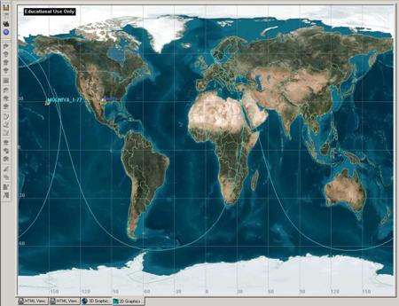
data from
STK, it will be necessary to download online data for a satellite into the
toolkit. Once the azimuth and elevation
report has been created and saved for a given satellite and time period, it
will be imported into our software as a text file. LabVIEW-written code
will then interpret the data and use it to drive the antenna. The text file will contain enough information
for our software to create a sky-chart and ground-track plot. Before satellite
tracking can occur, however, motion sensors must be installed on the satellite
dish.
<previous Go
to Table of Contents next>
The hardware team designed two identical sensor arrays composed of three
Anisotropic Magneto-Resistor (AMR) sensors.
One array will monitor the horizontal motion of the satellite dish, and
one will monitor the vertical motion.
The array design is shown in Figure 5.
Figure 5. Sensor Array Design
The circle represents a top
view of the shaft of the dish. The Home
Sensor indicates when the satellite dish is in its default position. The two
Stop Sensors prevent the satellite dish from over-rotating and damaging wires.
The Team Advisors determined that the dish may rotate by 370° before damage
will occur. Therefore, the angle between the two stop sensors is equal to 10° to
allow for 370° of rotation.
The
team chose the AMR for several reasons. First, the high sensitivity of the AMR
provides immunity to the gap between the magnet and sensor. Second, the low
cost and high reliability are desirable. Third, the sensor is small in size and
has dimensions of only .244” x .196” x .068”. Finally, the AMR has no moving
parts that could wear out over time [Linear, 2000]. The team submitted a Sample
Request to Honeywell and obtained 6 free sensors. The specific Honeywell AMR
model we have requested is the HMC 1501, which is shown in Figure 6.

Figure
6. HMC 1501 Sensors [Honeywell]
The AMR sensor is made by joining four Permalloy
resistors into a diamond shape to form a wheatstone
bridge configuration. The individual resistors are made by depositing a thin
film of Permalloy, a nickel-iron material, on a silicon wafer. The structure of
the AMR is shown in Figure 7.
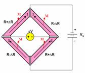
Figure
7. AMR Sensor
[Applications, 2002]
The top and bottom of the
diamond are connected to a supply voltage, Vs, so that a current, I,
flows through the sensor. When a magnet passes the sensor, a second magnetic
field, M, is induced in the sensor, and ∆V is produced between the two
side contacts according to the following
 (1)
(1)
where S = material
constant (12mV/V)
θ = angle between M and I
(degrees) [Applications, 2002]. By
placing an AMR sensor on the stationary base of the satellite dish and a magnet
on the rotating shaft, the direction of the magnetic field can be determined
from the output voltage. The HMC 1501 exhibits a 1.8
mV/° sensitivity [Linear, 2000].
The HMC
1501 contains one AMR bridge for a position sensing capability of θ equal
to ±45° [Applications, 2002]. The ∆V output versus θ is shown for a
Vs value of 5V in Figure 8.
Figure 8. ∆V Signal Output Versus θ
The graph shows that ∆V
is zero when the magnet is outside the ±45° range and θ is zero. When
θ is ±45°, the output voltage is at the maximum value of ±0.8 V.
There are three possible errors to consider when reading
the output signal. First, an offset error voltage may result from manufacturing
tolerances. The value of the offset will be determined through initial
experimentation. The motion-control application will compensate by adding an
error correction value to the output signal. Second, the material constant may
vary with temperature and affect the bridge sensitivity and offset error. The
coefficient of temperature for the bridge sensitivity is -.32%/°C, and of the
offset is -.01%/°C. The coefficient of temperature represents the percentage
error that will occur for each degree of variation from 25°C [Linear, 2000].
The method of compensation for this error is to be determined. Third, exposure
to a disturbing magnetic field could break down the magnetic alignment of the
Permalloy [Caruso, 1998]. The sensors will experience a disturbing field due to
the fact that the electromagnetic field of the dish motor and of the dish
controllers are completely contained within the housing.
The AMR
sensor operates in saturation mode, which provides two advantages: the sensor
is insensitive to the gap between the magnet and the sensor array and is
unaffected by the temperature coefficient of the magnet. The applied magnetic
field must saturate the Permalloy to make M align
with the external magnetic field and to produce reliable ∆V readings. A
minimum field of 80 Gauss is required for saturation [Applications, 2002].
To meet
this minimum magnetic field requirement, the hardware team chose .47” diameter,
.11” thick Neodynium magnets. The magnets provide
10,800 Gauss of residual magnetic induction and will be attached to the
satellite dish with epoxy. The team chose these magnets for their high strength
and small size.
As seen in Figure 9, the pins of the sensor are flat and
must be surface-mounted. Figure 8 shows a sensor soldered to a surface-mount
board before testing. In the future, the surface-mount board must be mounted to
a PC Board before installing on the satellite dish.
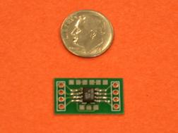
Figure 9. Sensor Soldered to Surface-Mount Board
To test
the performance of the sensors, a surface-mounted HMC 1501 sensor was connected
to a voltage supply and to a multimeter. Pins 2 and 7 of the sensor were
grounded, and pin 1 was outputted to the multimeter. The voltage supply was
connected to pin 5 of the sensor. The pin-out drawing of the sensor is shown in
Figure 10, and the test setup is shown in Figure 11.
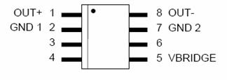
Figure
10. HMC 1501 Pin-Out Drawing
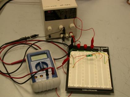
Figure
11. Sensor Circuit Test Setup
When the voltage supply was set to 5.0 Volts, the output
voltage of the sensor was 12.0 Volts. When the magnet was held an inch above
the surface of the sensor, a ∆V of ±0.4 Volts was produced. The ∆V
is too small for the motion controller to register so an amplifier circuit is
needed.
The sensors will be used outdoors and must be protected
from the environment. The design team has determined that the sensors should be
housed in 1” x 1” x 1” plastic
boxes. The sensor boxes should contain a water-tight seal and should have lids
with hinges in order to provide access for repairs. A ¼” diameter hole on the
side of the box will provide access for the voltage input/output wires to run
from the sensors to the antenna box. A rubber casing will protect the wires. In
the antenna box, the sensor input voltage wire is connected to the motor
voltage, and the sensor output voltage wire is relayed to the SDL.
The figure below depicts the future locations of the
sensor arrays on the satellite dish. The top circle and picture on the right
indicates the location of the vertical motion sensor array, and the bottom
circle and picture on the left indicates the location of the horizontal array.
The yellow arrows indicate the rotating surfaces on which the magnets will be
placed, and the purple arrows indicate the stationary surfaces on which the
sensor boxes will be located. The boxes will be affixed to the respective
surfaces with epoxy.
Figure 12. Sensor Array Locations
The satellite dish motors are pulse-encoded motors. The dish motors receive a 24 Volt input. The 24 Volt input powers the motors and
allows the satellite dish to move. Upon
receiving this input, the satellite dish then provides two outputs. The first output is movement. The second output is encoded pulses in the
form of square waves. These square waves
are created using rotary encoding.
Figure 13. Rotary Encoding
Figure 13 shows the process of
rotary encoding. A light source within
the drive motors sends light to a segmented disk. As the dish turns, the disk is turned
likewise. The segmented disk allows
light pulses through which are turned into an electrical signal and sent to a
squaring circuit. As the name would
suggest, this circuit produces the square wave pulses that are outputted by the
satellite dish as feedback. There are
two types of rotary encoding: absolute and incremental. Incremental encoding motors send three pulses
as feedback: Phase A, Phase B, and Index (see Figure
14).
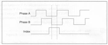
Figure 14. Incremental Encoding Pulses
The Index pulse acts as a
counter. Each pulse of the Index
corresponds to a rotation of the motor.
Phase A and Phase B are sent as feedback and are used to determine CW or
CCW motion. The second type of motor is
an Absolute Encoding motor. These motors
contain a segmented disk such as the one shown in Figure 15.
Figure 15. Absolute Encoding Disk
The Absolute Encoding disk
makes it possible to know to where the dish has been moved at all times. That is, each motor orientation has a unique
place identifier on the disk. A 5o
movement of the satellite dish has a unique place identifier as does the
movement of 6 o, 7 o, etc. This feature helps to avoid loss of
place. If there is loss of power, for
example, it is possible to determine exactly where the dish is based on the
position of the Absolute Encoding Disk.
This type of satellite dish motor would be ideal in that position
determination would be simplified.
The
satellite dish on the roof is an incremental encoding motor. There are two ways the incremental encoding
motor could send its signal. The first
method is called Single Ended TTL. This
method sends a single signal for each of the three feedback pulses (Phase A,
Phase B, Index). This manner of signal
feed is sufficient if the signal travels only small distances (less than 10
feet). The second method for signal feed
in an incremental encoding motor is the differential line driver method. This method sends two signals for each
pulse. For example, Pulse A would be
sent as well as Not Pulse A. This dual
signal system helps increase noise immunity over distances great than 10
feet. This method would be ideal for
sending feedback from the roof of the Aerospace building to the Satellite
Design Lab.
The
incremental motors on the satellite dish employ the Single Ended method. This could be a problem in that the distance from
the roof of the aerospace building to the SDL is much more than 10 feet. Also, the term “incremental encoding” motor
may be applied to the satellite dish motors erroneously (the term is referenced
in the literature supplied by the donator of the dish – the US Air Force). As described above, an incremental motor has
an index pulse. Based on tests performed
on the satellite dish motors it is the conclusion of LiNC that there is no
index pulse. Testing done on the
feedback system, however, has shown the existence of Phase A and Phase B. A nine-pin connector was made to take signals
from the pulse encoding lines and display them on an oscilloscope. The square waves outputted by the motors
during repositioning have been displayed on the oscilloscope numerous
times. These tests occurred on the
roof. Similar results have not been
duplicated in the SDL.
Research was also been done regarding integrated circuits
(ICs); specifically transistors and operational amplifiers. The team concluded that wear on the motors
can be reduced if voltage is applied gradually.
Currently, voltage is applied to the motors by way of relays. Relays are on/off mechanisms. When a relay receives 5 Volts, for example,
it then outputs 24 Volts. However, even
if a gradual voltage is applied to a relay the output is not sent until the
voltage reaches 5 Volts, and the output is instantaneous rather than
gradual. To overcome this obstacle, it
was initially thought that a transistor be used as a replacement. However, through discussions with Electrical
Engineering professors at UT, it was decided that operational amplifiers would
be a better choice.
At the time of the mid-term the plan was to use
transistors from Fairchild Semiconductors.
It has now been determined that operational amplifiers from National
Semiconductor will be the likely choice of IC.
The component LM 741, an op amp made by National Semiconductor, has been
purchased. This component, along with
input from the technical support team at National Semiconductor, has made
preliminary circuit designs of a differential amplifier possible. Figure 16 shows the basic circuit of a
differential amplifier.
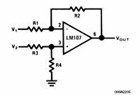
Figure 16. General Differential Amp Circuit (courtesy
of National Semiconductor)
The differential amplifier
allows an output that is determined by a set of two input voltages. Because the inputs can be varied, the output
can be made more exact without having to determine the exact gain the op amp
needs to have. Figure 17 shows a chart
of varied inputs and the corresponding outputs for an op amp with a gain of 4
Volts. The chart demonstrates the
flexibility of the op amps.
Figure 17. Input/Output for an Op-Amp with 4 Volt
Gain
Power switches were installed on the roof to provide
access to the 120 Volts running to the Yagi and the
parabolic antennas, as well as a third, optional device. Since safely working on the electronics in
the antenna box requires power to be shut off, the addition of the switches has
been a big convenience. It is no longer necessary to contact University Power
Station to have the circuit breaker removed (a process that could take as many
as three days). The switches are
water-proof and mounted in an aluminum chassis that is
attached to the inside of an access box.
The chassis is easy to remove if further work or repair on the power
system becomes necessary. The figure
below shows a diagram of the wiring connections.
The power switch assembly was installed in the 120V power
box as indicated in Figure 18. Figure 19
shows the hardware in place. The left
switch activates the power running to the yagi
antennas; the center switch activates power to the parabolic antenna; while the
switch on the right activates power to an optional future device. Although 120 V runs through the power
switches, the highest-voltage electronics we actually worked on received 24
V.

The systems integration between the software and the
hardware groups involves an understanding of the parts and connections
involved. Commands from the software
travel to the PXI-7734 Motion Controller that is a circuit board inside the
National Instruments CPU. This device
sends and receives information, to and from the Lab View software and also
sends and receives signals from the UMI-7764 Breakout Box. The UMI-7764 Breakout Box is an interface
device that allows wiring to be attached to specific motor-control
inputs/outputs. Figure 20 shows the
breakout box as well as the connections used for the purpose of this project.


The wires connecting to the breakout box lead into the LED
adapter box. The team constructed this
device in order to provide the necessary outputs for the dish. As seen in Figure 20, there are two analog
outputs from the breakout box, one for each axis. These outputs vary in polarity, depending on
which direction command was selected by the user or software. The adapter box diverts the current into the
correct place on the nine-pin connector by using light emitting diodes. This
simple circuit is shown in Figure 21 with the nine-pin connector shown on the
left side of the schematic, and the corresponding breakout-box wires, on the
right.

In addition to converting the output, the adapter box
confirms sent signals via the light emitting diodes and provides a clean
connection to the breakout box as seen in Figure 22. The nine-pin cable from the adapter runs to
the juncture box (also called the j-box) where the signals are directed to and
from the roof. These commands consist of
a direct current signals that have 5 Volt amplitudes. Once on the roof, the signals reach the
antenna box where  they end up in the relay board. The relay board provides 24 Volts per signal,
which in turn travels to the motor housing and activates the motors. The relay board ramps up the voltage using
two sets of relays. A relay is a switch
that closes when a current is passed through its magnetic coil, activating a
circuit of higher voltage than that which activated the relay. Hence, the first set of relay switches are
activated by the 5 V signals from the controller. Once a 5 V relay is tripped, it allows a
higher voltage circuit to activate a 24 V relay, which in turn passes the
higher voltage signal to the motors. A
schematic of this relay circuit can be seen in Figure 23.
they end up in the relay board. The relay board provides 24 Volts per signal,
which in turn travels to the motor housing and activates the motors. The relay board ramps up the voltage using
two sets of relays. A relay is a switch
that closes when a current is passed through its magnetic coil, activating a
circuit of higher voltage than that which activated the relay. Hence, the first set of relay switches are
activated by the 5 V signals from the controller. Once a 5 V relay is tripped, it allows a
higher voltage circuit to activate a 24 V relay, which in turn passes the
higher voltage signal to the motors. A
schematic of this relay circuit can be seen in Figure 23.
The
outputs on the right of the diagram represent the four different motor commands
(elevation up, elevation down, azimuth right, azimuth left.) In order for the antenna control to function
properly, the closed loop system must be completed by sending pulse-encoded
information through a relay-board bypass inside the antenna box to a nine-pin
cable running down to the j-box in the lab.
From there, the signal travels down the original cable, through the
adapter box and into the Breakout Box.
Once the Motion Controller receives
the pulse-encoded information, national instruments software interprets it for
use in the antenna control program written by LiNC. This program includes a graphic user
interface shown below in Figure 24.
The
manual control functionality allows the user to directly send signals to the
motors. That means elevation and azimuth
changes can be made by commanding the antenna to move on that axis until the
button is no longer pressed. The GO TO functionality receives an azimuth and
elevation from the user and then positions the antenna accordingly. The tracking functionality would receive an
ephemeris data file location provided by the user, then
track the satellite while it passes over the station. This last functionality has not yet been
programmed.
Figure 25 reiterates the
abovementioned connection process. This
closed loop system receives commands from the user, sends them to the antenna
box via the controller, Breakout box, and adapter box. There, the relay board amplifies the signals
in a discrete way and sends them to the motors.
The motors position the dish, creating pulse-encoded information that
travels back down to the lab and into the controller. Finally, the antenna control software
interprets the pulse-encoded signals and converts them to antenna position data
that allows the program or the user to adjust the outputs.
<previous Go
to Table of Contents next>
The
team designed the software structure in a modular way such that each function
performs a major task of the satellite dish automation process. The software takes inputs from the user as
well as the dish motors and sensors.
Through a graphical user interface, the user may specify how to move the
dish or which satellite to track. Sensor
inputs let the software know if the satellite dish is getting too close to the
limits of its motion and when the dish is in its centered position. Placing sensors at the satellite dish’s
centered position (the home position) is important, because the function
keeping track of azimuth and elevation is reset when the dish is centered. Another reason why home sensors are important
is that the satellite dish is stowed in the centered position. The centered position is at an azimuth of
180º and an elevation of 90º or when the dish is pointing straight up. Outputs are sent to the user to inform of the
azimuth and elevation angle at which the satellite dish is currently set. The software also allows the user to know
when and to which position the antenna is moving. Since the computer sends commands to the
antenna motors while receiving information from both the motors and sensors and
uses that received information to evaluate further commands, the system is
considered to be a closed-loop system.
The structure of the software reflects this fact. Three main antenna control
modules - the user interface and the optimization and angle counting functions
- work together to send and receive information to and from the user as well as
to and from the dish. Figure 26
illustrates the interconnectivity of these software components.
The
MOTOR CONTROL function is the lowest level of antenna-motor control available
in the software. In addition to
receiving commands from the user interface this is the only module that sends
commands directly to the motors (via the controller hardware interface). The MOTOR CONTROL module sends commands to
the motors to move them, specifying which direction each motor should move
(clockwise/counterclockwise) and at what velocity. This part of the code also

Figure 26. Software Architecture Flow Diagram of
Function Interconnectivity
ramps the
input voltage up and down to prevent unnecessary wear-and-tear on the motors
and their surrounding hardware.
The
GO-TO module serves a slightly more sophisticated purpose. Given azimuth-elevation input from the user
interface, this function activates the motor control module in such a way that
the motors are spun in the necessary direction and stopped when the desired
azimuth and elevation are reached.
Top-level
satellite dish automation takes place in the FOLLOW module. This module receives data from a text file
consisting of azimuth-elevation positions with their corresponding times. The data expresses the path of a satellite as
it moves across the sky over the tracking station. These position pairs are sent periodically to
the GO-TO function at the correct times, making the satellite dish follow a
satellite overhead.
Information
is received from the motors in the pulse-encoded feedback that was previously
mentioned in the Automated Motor Tutorial.
The COUNTER function receives these pulses and keeps track of them. Encoded pulses allow the COUNTER function to
determine which way each motor is spinning and how far it has gone. Based on the motor and satellite dish servo
properties, the ANGLE function converts this information into the dish’s
current azimuth and elevation. The ANGLE
function recalibrates the azimuth and elevation based on sensor inputs.
The
Motion Optimization Joint Operation module (MOJO) receives data from both the
ANGLE module and the sensor array as seen in Figure 25. MOJO tracks the satellite dish position and
movement in relation to the physical limits of dish operation. This function will deactivate any of the
satellite dish-control functions (MOTOR CONTROL, GO TO, and FOLLOW) if it knows
the dish is moving too close to the edge of its prescribed region of
operation. This module also makes sure
that the path taken by either the GO-TO or FOLLOW functions does not move the
satellite dish past its stops. Keeping
track of current dish position in relation to dish motion limits and
calculating shortest distance to a given azimuth and elevation optimizes the
motion of the antenna so that it never needs to approach a desired position
from one direction only to have to stop and reverse course because a motion
limit has been reached.
In
conjunction with the design of the software architecture, we developed a
preliminary graphical user interface (GUI).
A representation of this plan can be seen in Figure 27. We decided that the program should consist of
a single user panel that would contain all the information required for all
three types of motion-control.

Figure 27.
Preliminary Graphical User Interface
In the
upper, left-hand corner is located the Manual
Control option. This option is a
computerized version of the previous method of controlling the satellite dish
(up-down/left-right paddle from the roof).
The user has the option to toggle on and off switches that correspond to
clockwise or counter-clockwise motion in the horizontal plane (azimuth) and up
and down motion in the vertical plane (elevation). Motion will be able to take place in two
planes at once, but only one button will be operable at a time in any given
plane.
Directly below the Manual
Control section is the second motion-control option. In the Go
To window the user can specify a particular azimuth and elevation at which
the satellite should point. The Cancel button allows the user to abort a
move. If at any point in time during a
go-to motion the user decides to change the go-to location without previously
selecting the cancel button, the satellite dish will simply transition to the
newly entered location. Azimuth
indicates the horizontal plane location, and elevation indicates the vertical
plane location.
The third motion-control option is Tracking, and it is located
across the bottom of the window. A user
selects a text file that contains a prescribed set of azimuth and elevation
locations for given times that can be followed to track a satellite across the
sky. Once the Track button is toggled, the motion-control program will begin to
evaluate the selected file and maneuver autonomously. The In
View LED will indicate whether the tracking station is currently tracking
an in-view satellite (a satellite that is above the local horizon). Range
displays the straight-line distance between the satellite dish and the
satellite it is tracking. In Transit specifies the time left until
the satellite comes into view. On the
right-hand side of the Tracking
window the user will be able to evaluate a ground plot of the entire path of
the satellite currently being tracked.
This display may also show a handful of the ground tracks of the
station’s previously tracked satellites.
The Tracking option also has a
Cancel button, which, by toggling,
will abort a tracking exercise.
All three motion-control options contain an Activate button. The activate button brings focus to one
particular mode of motion and removes focus from the others. This feature serves two purposes. First, the motion-control application will
never need to be concerned with conflicting requests from multiple motion
functions. Reduced complexity reduces
the ways in which the program can fail.
Secondly, user error is removed from the equation on at least one
front. A user will need to actively
disengage the Activate button (thereby
bringing all satellite dish motion to a stop) before selecting a new mode of
operation. In the deactivated state,
only the Activate buttons for the
three motion options will have focus.
The user will have the option of bringing into focus any of the three
types of motion by selecting one of the three corresponding Activate buttons. This three-motion option deactivated state is
also the view with which the user will be presented upon first launching the
application.
Finally, we have the Sky
Chart in the upper-right quadrant of the screen. The sky chart will indicate the current focus
of the satellite dish with red crosshairs on a polar chart. The scope of this chart is the range of the
satellite dish. Current azimuth and
elevation are indicated in displays at the bottom of the Sky Chart. When the
satellite dish is in motion, the Antenna
Moving LED will light up. If the
motion-control program is tracking a satellite, the ground track for that
satellite inside the dish’s range will be shown on the current position chart.
Having settled on a software design, we needed to select
a software platform with which to program.
Developing the motion-control application with LabVIEW
quickly became the obvious choice. LabVIEW is a National Instruments development package that
uses pictures to program. Arranged in a
flow-diagram manner, LabVIEW code removes the need
for standard written code, though such code can still be interfaced with the LabVIEW pictures. Originally,
coding with a standard programming language such as C, C++, Java, or Visual
Basic had been considered, but when it became evident that the motion
controllers, also provided by National Instruments, were pre-packaged with LabVIEW functions, choosing the LabVIEW
environment was the easy decision to make.
The prepackaged LabVIEW functions are called
NI-Motion, and they are the functions that, when called on, actually generate
motion. An added bonus to LabVIEW is that the creation of a GUI goes hand-in-hand
with the drawing of the application code.
Boxes and buttons referred to in the code are automatically included in
the GUI. In fact, the act of designing
the user-interface is what generates corresponding item pictures for use in the
program’s flow diagram. [Bishop, 2004].
The current GUI for the motion-control application can be
seen in Figure 24. Manual Control, Go To,
and the Sky Chart have been fully
developed. The Follow function has yet
to be written, but a few of the items that will be a part of the completed
routine have been placed in the application GUI to give a good idea of how the
whole program will look in the end.
Those functions that have been completed have stayed true to the
original concept for the most part. As
the full application is developed further,
more
functionality will be added to the GUI so that it more perfectly mirrors the
concept drawing.
The GUI is driven by a LabVIEW
event structure that sits and waits for user input. All of the GUI buttons have entries in the
event structure so that if the button is pushed, some bit of code is
triggered. For instance, if Button A is pushed, release Button B. Figure 28 is the block diagram of the GUI
event structure. With one exception, all
code executed inside of the GUI event structure pertains entirely to the GUI
display. This exception happens to be
displayed in Figure 28. The GO HOME
event directly calls an NI Motion function that takes the dish to its home
position. All other calls to NI-Motion

Figure 28. GUI
Event Structure
position. All other calls to NI-Motion functions are
done outside of the event structure, even though they may be triggered by a GUI
event.
The software team decided that the first programming task
to complete would be to replicate the manual motion-control box previously used
to control the satellite dish from the rooftop of the Aerospace Department’s
building. Manual motion-control is the
most primitive control option for the satellite dish, and successfully creating
this functionality is a significant step in fully automating the dish.
Figure
29 is a screen shot of the basic Manual
Control GUI. Manual Control is the GUI side of the MOTOR CONTROL function. After the GUI event structure processes a
button click, the code behind the display runs through a series of

Figure 29.
Manual Control Graphical User Interface
nested if-than statements that pinpoint the
necessary action required of the satellite dish. This section of the code can be seen in
Figure 30.

Figure 30.
MOTOR CONTROL Block Diagram
The
toggle switch directly under the Manual
Control label is the Activate
button described in the Preliminary GUI
Design section of this report. The
green LED next to the toggle switch indicates when Manual Control has been selected.
Toggling the Activate switch
to the left turns off the LED and resets and removes focus from the four
directional buttons (they are deselected and fade into the background). When Activate
is toggled on, only one button of a pair (up-down, left-right) can be selected
at a time.
After
the MOTOR CONTROL function was written, the software team decided to work on
the GO TO function. Figure 31 is a
screen shot of the Go To GUI. The Go
To

Figure 31. Go
To Graphical User Interface.
GUI interfaces with the GO TO
function. Code for the GO TO function is
rather straightforward. Figure 32 is the
block diagram for the GO TO function. If
the Go button is clicked, only one if-then statement is executed. Elevation
and Azimuth are run

Figure 32. GO
TO Block Diagram
through sub-VIs that convert the angle input to counter output for use
by the motion controller (recall that the motion controller works with motor
pulses or counts, not angles). The Go Home button executes directly from
the GUI event structure as was previously mentioned. Clicking on Go Home returns the satellite dish to its home position (El =
90˚, Az =
0˚). Currently, the Reset button sets the values in Elevation and Azimuth to zero, but this button will soon be changed to a one with
ABORT functionality. An Abort button will stop the dish from
moving towards whatever the previously selected azimuth and elevation position
was. Finally, the Activate toggle switch at the top part of the GUI gives and takes
away focus to the Go To
interface. If this switch is toggled off
while satellite dish motion is taking place, the dish will stop. The LED next to the Activate switch indicates whether the Go To interface is active.
The Sky Chart can be seen in Figure
33. The sub-VI that drives the polar
graph in this display is a modified version of a prepackaged LabVIEW polar graphing VI.
A

Figure
33. Sky
Chart GUI
few
simple changes to the code allows for the display of the cardinal directions
(N, S, E, W) and removes all numbering from the graph. Figure 34 is a picture of the block diagram
that continuously updates the Sky Chart. The UPDATE CHART function polls the
motion-control software for the dish’s current position. Counter responses from the motion controller
for the azimuth and elevation locations are fed through sub-VIs

Figure
34.
UPDATE CHART Block Diagram.
elevation locations are fed through sub-VIs that convert counter input to angle output. Those angles are then converted to 2D polar
coordinates and displayed on the graph as a red line whose terminus is the
location of the dish’s focal point.
Graph divisions are in 15˚ increments on both axes. The azimuth and elevation for the dish’s
focal point location are also displayed in the Azimuth and Elevation
boxes below the graph.
The FOLLOW function is not yet
written. The GUI components seen in
Figure 28 are for show only at this point.
In addition to the fact that time ran out this semester, a number of
other obstacles remain in the way before FOLLOW can be finished properly. Some of these complications are discussed in
sections 6.0 and 8.0 of this report.
The only change to the
overall architecture that the software team has made is that the MOTOR CONTROL
function will be interfacing with the motor separately from the way in which
the GO TO and FOLLOW functions do. Previously,
FOLLOW was to call GO TO and GO TO would call MOTOR CONTROL to move the
satellite dish. Sticking with this
original plan would have provided greater complexity than having GO TO access
the motor in a different manner than the way MOTOR CONTROL accesses the motor. Our initial concern was to avoid repeated
functionality, but having learned more about the NI-Motion software that comes
with the motion controllers, the fact has become clear that most of the
functionality we thought we would need to create is already provided by the
NI-Motion software. Changing this aspect
of our software architecture greatly reduces the amount of code we need to
write; therefore, having two different functions operate the motors differently
is not a serious deviation from our original goal.
Over
the course of the semester various test apparatus were evaluated for their
ability to work out any problems with the software. All hardware testing was done on the MOTOR
CONTROL function only. Before any of the
other software functions can be tested, the simplest function needs to work.
At
first, a simple electronic circuit was created to test the MOTOR CONTROL
function. The test circuit represented
the two satellite dish motors as light emitting diodes (LED). For each motor two diodes were used. One diode represented forward motion and the
other represented reverse motion (one light per direction). The setup of this test apparatus can be seen
in Figure 35. This test was MOTOR CONTROL’s first successful operation of virtual
motors. The success was limited,
however, because the motion controller was not receiving the necessary motor
pulses (see Section 4.7) needed to sustain motion. After about five seconds, the controller
would time out and the LEDs would shut off.

Figure 35. National Instruments
Controller-LED Software-Test Circuit.
Having completed our first test, we began searching for
encoded feedback motors that could truly simulate the dish motors. We were not able at this time to begin testing
on the satellite dish, because the dish-controller interface was still not
functioning properly. Small motors that
we were able to acquire, such as the one in Figure 36, did not work with our
software. Regardless of whether the
motors had pulse-encoding, the software

was
incapable of performing as it was intended to.
With NI’s Measurement
& Automation Explorer (MAX), which can be seen in Figure 37, the motors
could be tested without the software.
This alternative source of command provided proof that the

Figure 37. NI Measurement & Automation Explorer
software was
not at fault for failing to drive the motors.
The motors did not respond to MAX driven input either, and as a result,
our team discovered that the voltage supplied by the controller was a limiting
factor in how we could control external hardware. Learning about the characteristics of the
motion controller through trial and error helped to develop a plan of action
for finally testing the software on the satellite dish.
The motion-control literature indicates that the PXI-7734
controller operates at +/- 10V. This
voltage drops when the motion controller is placed in series with a significant
external resistance. When the motion controller
was tested on the diodes, no significant voltage drop occurred across the
diodes, because diodes do not have a large resistance. Motors, however, do have a significant
resistance. While testing the motion
controller on the small motors, we observed that the voltage across the motors
would drop to about 4V, which was not sufficient enough to drive these
motors. Because we knew that the
satellite dish’s amplifying relay board requires 5V to operate, we decided to
check to see if the motion controller’s 4V was adequate enough to trigger the
relays on the board. Two of the four
relays worked, which meant we could now partially operate the satellite
dish. After the circuit was modified so
that all four relays worked, we decided it was time to test the software on the
satellite dish.
The dish moved on the very first attempt at
software-controlled motion, only to time out five seconds later. We were not surprised, though, because no
pulse-encoded feedback was connected to the controller from the satellite
dish. Motion was, and still is, possible
on both axes, though only for five-second intervals. The intervals do not have to be spread out;
they can be rapidly executed back to back.
Later in the report, we talk a bit about what we are trying to do to
perpetuate future satellite dish motion.
<previous Go
to Table of Contents next>
Although an open loop system between the computer
and the antenna has been set up and tested successfully, motor feedback has not
yet been achieved. Several problems
regarding the pulse encoding method restrict the current system
functionality. To begin, the National
Instruments software expects an index pulse as one of the motor responses and
as of yet, LiNC has not been able to identify an
index pulse coming out of the motor connection cable. The wiring connections in question are shown
in Figure 38.

The
connections make no accommodations for an index pulse. Although it might be possible to double one
of the existing pulses as the index, current attempts at signal return have
been unsuccessful.
Another dilemma arose due to the
inconsistency of the pulses. The team
tried several times to analyze the pulse output on the roof using an
oscilloscope. The pulses could be observed
during only half of the attempts. This
in consistency could be attributed to our testing method or the oscilloscope
settings. However, there exists a
distinct possibility that the motor-encoding apparatus or connections are
faulty. This would present a much bigger task for future development. Furthermore, the pulse-encoded signal could
never be obtained in the lab. This could be associated with the previous
problem. However, signal degradation could occur aver the cable lengths
involved in the system. This possible
signal loss can be prevented by winding the pulse cables around each other, by
using shielded cable in the lab, and by keeping the control CPU within 10 feet
of the juncture box.
There is also a mechanical problem
with the elevation mechanism. Mechanical pins control the range of elevation
motion. These pins are positioned with solenoid servos, one of which is not
functioning, as shown in Figure 39. This means that the satellite dish cannot
execute a full 0 - 180° elevation turn. However, 0 - 90° motion is attainable and
sufficient for most antenna applications.

In addition, the satellite dish was exposed to extreme gusts
from the storms moving through the Austin area during the weekend of the 24th of
April. The resulting vibrations caused
the pin connecting the elevation servo arm to the elevation joint mount to come
loose and fall out. The pin acts as a
structural member and without it the dish looses support in the elevation axis. The loss of structural support caused the
dish to come to rest on the support ring around the motor housing.
The pin was replaced and Loctite
applied to the ends of the pin. Loctite is a liquid
sealant that hardens to form a waxy stopper in junctures such as the elevation
connection.
Damage was caused to the transmitter support beams causing
the transmitter/receiver dome to come out of focus. Refocusing the satellite
dish will be a key step after remote automation is achieved.
<previous Go
to Table of Contents next>
Future
design teams may use this report to fabricate the sensor boxes and circuit
boards, and to install the sensor arrays and magnets on the dish. Because the
∆V outputted by the sensor is only 0.4 Volts, future teams will also need
to design and install an amplifier circuit to amplify the output voltage of the
sensors before relaying it to the SDL.
Integration
of the sensor array and drive motor feedback system to the SDL must be
completed. Integration includes
replacing the relay board, and determining the exact pulse/degree ratio. In order to replace the board we must
determine exactly how power is delivered and any additional functions the board
performs must be determined. These
details are crucial in the development of an op-amp based board. The op-amps, as well as any other
miscellaneous parts (PC board, resistors, etc.), that will be used in the
fabrication of the replacement board must be chosen and purchased. National Semiconductor op-amps have been used
in the preliminary design phase and will likely be used in the fabrication
phase as well. The replacement board
must then be fabricated and installed in the motor control box on the roof.
The pulse/degree ratio must also be determined. Signals sent by the motor have been displayed
on an oscilloscope. The pulse-encoded
feedback will likely be used as the index required by the software. In order for these pulses to be used as the
index the exact pulse/degree ratio must be determined. The pulse-encoded feedback has been
inconsistent and the cause of this inconsistency must also be determined.
Once the satellite dish motor has the correct circuitry
and the sensors have been installed they must each be integrated with the
motion controller in the SDL. Wiring
already in place will be used to connect the sensors and the motor to the
lab. The adapter box will have to be
modified to fit the additional wiring from the roof and to provide appropriate
connections between the hardware and software.
<previous Go
to Table of Contents next>
The next step in software
development is trouble shooting the MANUAL CONTROL and GO TO functions. Although we have managed to move the
satellite dish with our current software configuration, there may be sneak
circuits in the code that up to this point have gone unnoticed. Because the NI-Motion software continues to
time out before any major kinks can be evaluated, we are left without the
ability to successfully fix any bugs in the code. NI-Motion software is counterintuitive in
many cases and the reference manuals provided by National Instruments are far
from helpful. In fact, the only source
of information that provides any kind of support is the Help file (NI-Motion
Help can be accessed through the LabVIEW
interface). The Help file is just barely
useful, and so misuse of the NI-Motion functions is almost guaranteed. Regardless, further progress with the
software will most likely have to be put to the side while the
hardware-software interface is the main focus of work on the satellite
dish. Debugging cannot take place until
sustained dish motion has been achieved, and currently the bottle neck in the
design process is the problematic hardware-software interface.
The function that drives the Sky Chart GUI is going to take some time to fully complete. At the time this report was written, the display
only indicated the position in the sky at which the satellite points. The user readout will need to include the
information for whatever satellite the dish is currently tracking. This satellite tracking information is
detailed in the following section. The Sky Chart GUI functionality, previously
referred to as UPDATE CHART in the earlier Software section, cannot be
completed until the FOLLOW function can import external satellite ephemerides. In
addition, the Sky Chart cannot be tested until the satellite dish is capable of
sustained motion. Until that time, the Sky Chart will only be a static display
of a polar graph.
The ultimate goal for tracking is to give the user load-and-track
capabilities. This means that the user
will be able to select a satellite after loading its information into the
program, and track it by simply clicking the appropriate button. STK creates a file of azimuth, elevation, and
range data with respect to time. The
part of the LabVIEW software that will handle the
loading and interpretation of the data file is still to be written. Although Satellite Toolkit can generate such
a file, the automatic generation or downloading of satellite ephemerides would greatly simplify program operation. Writing the algorithm that will actually
interact with the GO-TO function to track the satellite across the sky is also
an important next step.
The
tracking software will also need graphic screen outputs. Our group will write
code to display the ground track of the satellite based on its two line
elements, indicate when the satellite is in range for the ground station (that
is, when the satellite rises in the local horizon), output the sky-chart for
the satellite, and show its range from the station. The information to create these charts will
be obtained from the same text file as the azimuth and elevation data. Graphical output will require some
calculations to be performed inside our program. The code to handle this will be written with LabVIEW’s Virtual Language (VL). VL is different than the normal graphical LabVIEW code and requires some extra work to use properly.
<previous Go
to Table of Contents next>
Although LiNC established the
foundation for satellite dish automation, there remains much work for closed-loop
tracking capability to be realized.
Currently, signal degradation and the lack of an index pulse pose the
biggest obstacles. LiNC
suggests pulse wire twisting, shielded cables, and maximum CPU proximity to the
Juncture Box to combat any possible signal loss problems. Furthermore, all twelve of the pins from the
motor (as shown in Figure 35) should be examined during motor operation to
ascertain whether or not an index pulse lurks in one of the signals. In the case that no index pulse exists as predicted,
the following options should be evaluated.
1.
Double one of the
existing A or B pulses as the index.
Plug either the A or B cable into the INDEX plug inside the Breakout
box.
2.
Create an artificial
index using a function generator. Create
a square wave with an amplitude of 1 V and a period of
1 millisecond. Adjust the period until
the correct response results.
3.
Operate without the
index. The antenna open-loop control
system currently operates by moving the antenna at 5-second intervals before
signal cut-off resulting from lack of feedback.
This may be sufficient to sustain tracking capability. If the GO-TO and TRACKING functions call the
MOTOR CONTROL function for intervals of less than 5 seconds, tracking and go-to
capability could be achieved through the use of discrete antenna
movements. The existing pulses would
then serve to determine the antenna position through either existing LabVIEW functions, or if necessary, programmer adapted
algorithms.
4.
Abandon the Motion
Control Software and Controller board.
An Input-Output port on the CPU (I/O port) could receive the signals and
signal analysis functions could be written in C++, C, FORTRAN,
Java or another language. This would
avoid the incompatibility between available signals and existing LabVIEW prewritten analysis functions.
LiNC recommends trying each
of these plans in the order they are listed.
If successful feedback or feedback
emulation is achieved, the following software needs to be completed:
- A LabView TRACKING function that reads a text file and
loads azimuth and elevation data with a time index into arrays. The arrays
can then be sent to the GO-TO function at the appropriate time.
- The source of the
tracking file can be a user written program that creates sky-chart data
based on 2-line elements downloaded from the web. Satellite Toolkit software can also be
employed to create a sky-chart file.
- Motion Optimization
Joint Operation (MOJO) must be written in order to assure correct azimuth
and elevation synchronization. This
code will determine if TRACKING or GO-TO inputs cause the satellite dish
to reach the limits of motion and if so, find the best alternate path.
LiNC
advises that while experimenting with new software-system integration, a person
remains on the roof to observe the antenna location and deactivate the power
switch located in the power box (see Figure 17) if remote deactivation fails
and/or the antenna runs up against its stops. LiNC
recommends that a camera be installed on the roof to improve the user interface
with the motion control system.
<previous Go
to Table of Contents next>
The
Design of Everyday Things is a book that deals with the psychology of how
people interface with machines, the design principles that make that interface
natural and straight-forward, and the design mistakes that make some designs
fatally flawed for use by real human beings [Norman,
2002].
The
Graphic User Interface is our systems control mechanism for the user. The
design of this interface was discussed previously in Section 5.4. Let us explore some of the reasons for this
design. Note that the manual control, go-to, and tracking sections are
accessible in their own sections of the GUI. This sectioning provides a
physical map that tells the user that only one level of control can be accessed
at a time. Physical maps appear in well designed controls that provide visual
clues as to the effects of their operation [Norman,
2002]. It is insufficient to provide good physical mapping: the user must also
be reminded of the operation of the interface [Norman,
2002]. A reminder is that the virtual push-buttons on the screen that activate
each level of satellite dish control pop out on all windows except the one that
the user is currently accessing. In other words, activating a level of control
by pushing the activate button on any one level, causes all other levels to
deactivate and their activate buttons to pop up. Other examples of physical
maps that appear in our interface are the manual motor control buttons. The
buttons are oriented in a cross where up, down, left, and right buttons move
the satellite dish in the corresponding directions. These buttons also have
mutually exclusive pop-up properties. This means that it is impossible for the
user to attempt to drive a motor in two directions simultaneously. Such
features are also examples of designing against failure. It is infinitely
better to make it impossible for the user to make a mistake, rather than
designing the system to handle certain errors [Norman,
2002]. Installing sensors on the dish that let the software know when the
antenna is about to reach the limit of its motion so that the program can kill
the engines is just another example of this design philosophy. The operator
does not have to worry about damaging the satellite dish, because the
automation-system was designed to make user-inflicted damage impossible.
Allowing
the user feedback about his or her actions is an important feature of good
design [Norman,
2002]. Without system feedback, the user can never be certain that the controls
are performing the desired tasks. This can lead to frustration and incorrect
use of the interface. Our user interface is armed with several displays that
show the user when buttons have been pressed. Lights on the buttons light up
and the buttons themselves appear to be depressed when activated. Numerical
output is dynamically updated as the satellite dish is moving to allow the user
to know when and how the motors are in operation. In addition to this, a
crosshair on the sky-chart provides a back-up visual cue as to the position
azimuth and elevation position of the antenna. Finally, a tertiary signal in
the form of a display light indicates when the system is in motion. All this is done to ensure that the user
knows of the effect of his actions.
In
spite of the designer’s best attempts, sometimes the user makes error. This is
not the fault of the user for to err is human [Norman,
2002]. Dealing with user mistakes is one of the engineer’s most important
goals. This is also evident in our system. Each one of the control-level access
windows features a cancel button in order to stop all antenna motion when the
user realizes that an undesired input has been entered. Since user errors are
inevitable, being able to reverse ones mistake is utterly necessary.
User-centered
design is designing for a specific group of people and optimizing the design
around that group [Norman,
2002]. The group of users for our system will be aerospace engineers with
elementary knowledge of orbital mechanics.
This means that the operators, will have a general knowledge of how the
satellite dish should work including what azimuth and elevation mean, what
range is, what a sky-chart and ground track look like, and when a satellite
will be in view. If some of this knowledge is not present, a help file will
dispense any and all myths about satellite tracking terminology as well as the
various function available to the user via the GUI. Such users will most likely
be interested in accessing the satellite-tracking window at the bottom of the
GUI. Accordingly this window was made the largest and easy to identify. Since
people obtain much of the information from the world around them [Norman,
2002], we made sure to include a plethora of visual cues in the design by
methodically labeling all windows, buttons, display lights, and charts.
<previous Go
to Table of Contents next>
Most of
the hardware and equipment necessary for the successful completion of the
project has been donated. The U.S. Air
Force donated the satellite dish, and National Instruments donated the
controllers, the CPU, and the breakout box.
The Sample Request for the HMC 1501 sensors was successful, and LiNC received 6 free sensors. The cost for the project was
negligible.
<previous Go
to Table of Contents next>
Figure 40 shows the timeline for the entire semester. The dates listed across the top row of the
table indicate the week that the activity occurred. The team did preliminary
research during the last week of January and throughout February. The bulk of
the work in designing the motion-control application occurred throughout the
months of February and March. Testing and troubleshooting of the sensors and
motion-control application occurred throughout April, and the final results and
conclusions were made during the first week of May.
|
|
Task Name
|
Start
|
Finish
|
1/26
|
2/2
|
2/9
|
2/16
|
2/23
|
3/1
|
3/8
|
3/15
|
3/22
|
3/29
|
4/5
|
4/12
|
4/19
|
4/26
|
5/3
|
|
1
|
Define Project Goals
|
1/28
|
1/30
|
|
|
|
|
|
|
|
|
|
|
|
|
|
|
|
|
2
|
Read Instruction Manuals
|
2/2
|
2/13
|
|
|
|
|
|
|
|
|
|
|
|
|
|
|
|
|
3
|
Prelim. Presentation
|
2/4
|
2/4
|
|
|
|
|
|
|
|
|
|
|
|
|
|
|
|
|
4
|
Troubleshoot N-Motion Control
|
2/6
|
2/13
|
|
|
|
|
|
|
|
|
|
|
|
|
|
|
|
|
5
|
Research Sensors
|
2/9
|
2/24
|
|
|
|
|
|
|
|
|
|
|
|
|
|
|
|
|
6
|
Begin LabVIEW work
|
2/13
|
2/17
|
|
|
|
|
|
|
|
|
|
|
|
|
|
|
|
|
7
|
Manual Control Application
|
2/18
|
2/29
|
|
|
|
|
|
|
|
|
|
|
|
|
|
|
|
|
8
|
Purchase Sensors
|
2/24
|
3/10
|
|
|
|
|
|
|
|
|
|
|
|
|
|
|
|
|
9
|
Midterm
|
3/3
|
3/6
|
|
|
|
|
|
|
|
|
|
|
|
|
|
|
|
|
10
|
Motion Controller Dish Interface Voltage
|
3/6
|
3/26
|
|
|
|
|
|
|
|
|
|
|
|
|
|
|
|
|
11
|
GoTo
Application
|
3/6
|
3/28
|
|
|
|
|
|
|
|
|
|
|
|
|
|
|
|
|
12
|
Follow Application
|
3/29
|
4/18
|
|
|
|
|
|
|
|
|
|
|
|
|
|
|
|
|
13
|
Test Sensors
|
4/5
|
4/19
|
|
|
|
|
|
|
|
|
|
|
|
|
|
|
|
|
14
|
Troubleshoot Sensors
|
4/20
|
4/26
|
|
|
|
|
|
|
|
|
|
|
|
|
|
|
|
|
15
|
Troubleshoot Control Application
|
4/19
|
5/2
|
|
|
|
|
|
|
|
|
|
|
|
|
|
|
|
|
16
|
Final Report
|
5/3
|
5/5
|
|
|
|
|
|
|
|
|
|
|
|
|
|
|
|
Figure 40.
Future Work Timeline
<previous Go
to Table of Contents next>
The UT
Aerospace Department’s tracking station (the Satellite Design Laboratory, or
SDL) was acquired from the U.S. Air Force.
Remote control from the SDL is necessary for future application in the
FASTRAC and RACE programs. Automating the satellite dish will allow UT students
to participate in these programs. This
semester, LiNC has undertaken the automation of the dish system. The team designed two sensor arrays
containing three sensors each. The team also tested a sensor circuit and
determined the voltage output of an individual sensor. The software team
completed the design of the motion-control GUI, the Motor Control function, and
the GoTo function. The team successfully controlled
the satellite dish from the SDL with the LabVIEW
software. LiNC determined that the
satellite dish motors do not output an index pulse as required by the National
Instruments (NI) Motion Controller. As a
result, the software could not be used to control the satellite dish for more
than 5 seconds at a time. Future design
groups may choose to manipulate the pulse-encoded output of the motor to
locate/emulate an index pulse or to abandon the controllers entirely. Once
extended remote control is obtained, the Follow function is written, and the
sensor arrays are installed, satellite tracking can take place.
<previous Go
to Table of Contents next>
“Applications of Magnetic Position Sensors,”
Honeywell Solid State Electronics Center, AN211,
Plymouth, MN, January 2002.
Bishop, Robert H., Learning With LabVIEW 7 Express, Pearson - Prentice Hall,
Upper Saddle River, NJ, 2004
Bratland, Tamara, and
Wan, Hong, “Linear Position Sensing Using Magnetoresistive Sensors,”
Honeywell
Solid
State
Electronics
Center,
A2.4, Plymouth,
MN,
2003.
Caruso, Michael J., and Smith, Carl H., “A New
Perspective on Magnetic Field Sensing,” Honeywell Solid State Electronics
Center, Plymouth, MN, May 1998.
Lightsey, G.E., “Lightsey Research Group:
Satellite Design Lab,” http://gps.csr.utexas.edu/sdl/index.html
(Austin, TX:
University of
Texas, 5
March, 2004).
“Linear/Angular/Rotary Displacement Sensors,”
Honeywell Solid State Electronics Center, 900246,
Plymouth, MN, August, 2000.
“Magnetic Sensor Overview,”
Honeywell Solid State Electronics Center, 900187,
Plymouth, MN, October 1996.
Motion Control:
7344/7334 Hardware User Manual, National Instruments, Austin, 2001.
Norman, D., The Design of Everyday Things, Basic Books, New York, 2002.
<previous Go
to Table of Contents
Page Created by:
Marcin Lenart
Created: May 2004
Modified: May 12, 2004