


ASE 463 Q
-Spring 2003-
Team Leader: Stephanie Autrey
Erin Miller
Sarah Stojanik
To Dr. Glenn Lightsey for bringing this vast and challenging project to Aerospace students and to the University of Texas.
To Tom Campbell for his patience, dedication, as well as his immense knowledge about electrical engineering and amateur radio.
To the Air Force for donating most of the satellite equipment. Also, Santa Clara University for hardware, ideas, and experience. Applied Research Laboratories for sharing their knowledge and lending equipment for the Spring Semester.
A satellite tracking facility is currently being constructed at The University of Texas with the intent of developing a student-based ground station that will have the capability to directly upload and download data from satellites launched by the Aerospace Department. The Longhorn Tracking Station will not only serve as an educational facility where students can gain hands-on experience, but will ultimately join an existing network of other university tracking stations. The essential hardware was obtained from the United States Air Force after the termination of the MightySat program, and additional hardware has been donated by Applied Research Laboratories and Santa Clara University.
This semester, the station will be set-up to track low-earth orbiting satellites, some of which operate on S-band, at a frequency of 2.4 GHz. Equipment will be upgraded to account for the high frequency, and software will be installed to determine the necessary orientation of the dish. The end result will be an automated process that will control satellite dish orientation and receiver frequency while adjusting for Doppler shift.
The Longhorn Tracking Station will create an operational satellite control facility within the Aerospace Department at The University of Texas at Austin. The station will enable students to remotely track, downlink from any satellite, and uplink to UT owned satellites in low-earth orbits. The following section presents the purpose of the Longhorn Tracking Station and provides an overview of the project.
The purpose of the Longhorn Tracking Station (LTS) is to develop a student based ground station in order to directly upload and download data from satellites launched by the Aerospace Department at the University of Texas at Austin. This project will not only serve as an educational resource where students can gain hands-on experience, but also will enable students to communicate with the department’s (as-yet unlaunched) orbiting satellites.
The station will implement technology developed by the Air Force’s MightySat mission, as well as knowledge and equipment employed by The University of Hawaii and Santa Clara University. The tracking station will enhance the capabilities to communicate with, to gather data from, and to maintain optimal operating performance of the governing satellites.
A satellite tracking facility is being assembled on the fourth floor and roof of the WRW building at the University of Texas. Through a donation from the United States Air Force, the Longhorn Tracking Station project has acquired the essential hardware for the station. Additional equipment is being donated by Applied Research Laboratories in Austin and Santa Clara University.
During the spring 2003 semester, the station was set up to track some low-earth orbiting satellites which operate on S-band, at a frequency of 2.4 GHz. In order to achieve this, the current hardware and software was upgraded. The LTS acquired a new antenna feed design, and will replace existing amplifiers in the feed electronics with ones capable of tracking the S-band frequencies, and track S and L band frequencies. Satellite Tool Kit (STK) has been installed on the mission planning computer, and software to control Doppler shift was also installed on the signal processing computer. The end result, once completely configured, will be an automated process that will control satellite dish orientation and receiver frequency while adjusting for Doppler shift.
In future semesters, modifications will be made in order to uplink commands to University satellites. Once the LTS team is able to successfully track S-band frequencies, then the next step will be to track L-band, a frequency of 1.2 MHz. The University of Texas desires to link the Longhorn Tracking Station with those of Santa Clara and The University of Hawaii, establishing a ground station network that would allow for satellites to be tracked continuously over longer periods of time.
The following sections explain the motivation behind building the tracking station at The University of Texas and the influence the MightySat program has had on the Longhorn Tracking Station project. Information about the tracking stations at Santa Clara University and Applied Research Laboratories will also be discussed.
For over 30 years, the Aerospace Department at The University of Texas has been teaching undergraduate engineering students the skills necessary to be successful in atmospheric flight and space flight operations. Many atmospheric flight students take advantage of the hands-on capabilities that the three flight simulators allow, but there have not been hands-on activities for those students interested in space flight.
In 1999, Dr. Glenn Lightsey was hired by the UT Aerospace Department. After working at NASA Goddard Space Flight Center, Dr. Lightsey realized the importance of giving students interested in space flight operations experience before they enter the professional engineering community. The Aerospace Department sought to fill the void in applied space flight applications by implementing a student-built satellite program. Before a student satellite can be launched, the University desired a way to monitor the satellites and upload commands and download data. Several options were explored, but the final decision made was to place the tracking station on the roof of the W. R. Woolrich Laboratories because this location provided easy access to the equipment. The location also allowed the department to have full control over the station rather than borrowing time from another station. In 2002, Dr. Lightsey acquired tracking equipment for LTS from the United States Air Force from a program called MightySat.
MightySat was a United States Air Force project that launched two small satellites into orbit in order to provide inexpensive demonstrations of space technologies [STS-88, 1998]. The satellites hoped to demonstrate four technologies, including composite structure, advanced solar cells, advanced electronics, and a shock device. The first of the two satellites was launched from the space shuttle, STS-88, in 1998. MightySat II was launched from a hybrid rocket in 1999. After successfully demonstrating the four space technologies listed above, the MightySat project ended in 2000. After the project ended, the government willingly donated the equipment to the University of Texas so that a tracking station could be built. In addition to the MightySat program, other tracking stations have been examined in order to better understand mechanisms of a working tracking station.
The following section will describe other tracking station facilities at Santa Clara University and Applied Research Laboratories.
Santa Clara University
Santa Clara University (SCU) has been extremely helpful in setting up the Longhorn Tracking Station. They have shared expertise and support, as well as equipment. We have modeled our station after the SCU Robotic Systems Laboratory (RSL). SCU RSL is a part of a ground station network that the LTS will eventually join. Other than SCU, the network includes the University of Hawaii and will include several universities in Japan.
Throughout the 2000-2001 school year, a group of students successfully installed a satellite tracking station at SCU. The RSL group selected a tower design that is supported by a base mounting system and placed it on the roof of the SCU Engineering Building 404. The group was interested in monitoring a wide range of amateur radio bands and for this purpose installed a high gain Yagi antenna with azimuth and elevation control. All of these components were attached to a polycarbonate top plate, and then mounted on a galvanized steel base, which was attached to the tower.
In the RSL control room, the SCU students transmit and receive data to and from the Yagi antenna using an ICOM 910 transceiver. It receives data from the modem, converts it to radio waves and sends it out the antenna. The same box is also capable of receiving radio waves and sending them to the modem for decoding. The Kantronics 9612 modem is used to encode and decode satellite information, and it can also be used to receive commands through their LabVIEW user interface. In order to point the antenna in line with azimuth and elevation, they use a Yaesu G-5500 Antenna Controller as an interface between the antenna controller and the antenna rotor.
RSL uses Nova software to propogate the Kepler elements for any satellite at a particular time. They use a LabVIEW graphical interface to make dynamic changes by logging onto Nova. Any user with administrative privileges can logon to RSL through an internet connection. Users can access the website of various ground stations to track satellites and make changes to the system. Due to the network, there are added security measures that are not currently necessary for the LTS, but will need to be added in the future.
Applied Research Laboratories Tracking Station
The station located at Applied Research Laboratories at The University of Texas at Austin (ARL) is a Global Positioning System (GPS) monitor station. It is one of thirteen stations in the Monitor Station Network (MSN) developed by the National Imaging and Mapping Agency (NIMA). This network is a contractor for the Department of Defense and is responsible for monitoring government owned satellites. In particular, the monitor station at ARL is a development and test location; therefore, it is not responsible for tracking continuous real-time data from government satellites. The monitor station primarily tests new hardware and software programs in order to improve the data availability of the network. In addition to the tests, research is also conducted on the data received from the station in order to improve the data quality and quantity. Currently, the data availability is between 92-95%. Research conducted on data produced by stations such as ARL is helping to improve these percentages by accounting for signal errors and obstructions due to a station’s geophysical location. [Mach, 2002]
The ARL station has been automated and unmanned since 1995 and is controlled remotely by the Monitor Station Network Control Center (MSNCC) in St. Louis. Missouri [Mach, 2002]. The station is unclassified, but can manually switched to a classified frequency. Since it is a GPS tracking station, it possesses different components from those of an amateur radio band satellite tracking station such as the LTS. The ARL tracking station creates redundancy by having two Ashtech-12 PPS GPS receivers, and two Hewlett Packard cesium frequency standards. Additionally, it has temperature, humidity, and pressure sensors, an uninterrupted power system (UPS) with a 14-hour battery backup, and a choke ring antenna [Mach, 2002].
Radio science makes possible many of our daily operations, including: AM and FM radio, television, amateur radio transmissions, and satellite transmissions. Understanding radio science is the first step in creating an overall strategy for tracking satellites.
Amateur Radio Bands are frequency ranges used for various applications, as shown in Figure 3.1. The lowest band of interest is the Medium Frequency (MF) band, which ranges from 1.8-2.0 MHz. The subsequent amateur band is the High Frequency (HF) band, which operates from 3.5-29.7 MHz. The next amateur radio band is the Very High Frequency (VHF) band, which operates from 50-225 MHz. The Ultra High Frequency (UHF) band operates from 420-928 MHz, and the highest frequencies that satellites operate on lie within the Microwave bands from 1.2-10.5 GHz [Amateur, 2003].
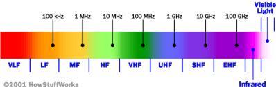
The MF and HF bands are used mostly for placing amateur radio calls, and also for some satellites transmissions on 29.4 MHz. VHF band is for radio controlled planes and cars (72 MHz), FM radio (88-108 MHz), television stations (54-88, 174-220 MHz), and even a few satellites operate at 144 MHz [Radio, 2003]. The MIR Space Station operated on both 145 MHz and 437 MHz [Radio, 2003]. Many satellites also operate over the Microwave band: GPS satellites operate over 1.2 GHz (L-Band), and deep space communications operate over 2.4 GHz (S-Band) [Amateur, 2003]. Since satellites operate over so many different radio bands, it is crucial for a tracking station to be capable of tracking radio bands up to S-Band. Understanding radio science provides the basic principles to understanding how a satellite is tracked.
Several steps are involved in tracking a given satellite across the sky, as shown in Figure 2.1. First, the two line elements of the desired satellite are entered into a software tracking program, such as Satellite Tool Kit (STK), on a mission planning computer.

The software will output the azimuth and elevation of the satellite when in view of the ground station. This information is then sent to the signal processing computer which automates the movement of the dish to the initial position according to the satellite’s azimuth and elevation, synchronizes the frequency on the receiver in tune with the satellite’s transmitting frequency, and adjusts for Doppler shift as the satellite moves across the sky. Doppler Shift is caused by the relative motion between a satellite and an observer, which causes a frequency shift known as the Doppler Effect [Doppler Compensation, 2003]. Data is then sent through the Mission Operations Tower, which houses the receivers, modems, a precision standard time clock, a Doppler Corrector Unit, a satellite tracker, and an AC power control unit. From the Mission Operations Tower, data is sent to the junction box on the roof of the building. The satellite tracking positioner controls the rotation of the dish and continuously adjusts to track the satellite across the sky. Data received from the satellite is acquired and decoded by the modem, and it is then passed down to the Satellite Design Lab for analysis. The hardware and software flow chart for the LTS particular configuration of tracking a satellite can be found in the Appendix. After understanding the tracking procedure, the current equipment can then be assessed in order to construct a working ground station.
The following sections will describe components of the Satellite Design Lab hardware, software, and the rooftop hardware. Most of the current equipment involved has been donated by the United States Air Force. The components described below will not be the full set of final components; although they will be upgraded and replaced in some cases, the current components will be the core pieces of equipment necessary to get the tracking station operational.
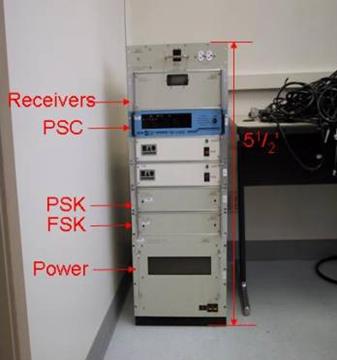
The Satellite Design Lab is located in W.R. Woolrich Building in room 407A. The equipment consists of two computers, two receivers, PSK and FSK modems, a precision standard time clock, a Doppler Corrector Unit, a satellite tracker, and an AC power control unit, which serves as the main power switch. The components, excluding the computers, reside in the Mission Operations Tower, as shown in Figure 3.1. All electronic equipment is handled through serial connections with the ground station computers [Cross, 2002]. The design lab has copper grounding strips underneath the floor tiles in order to create an anti-static grounding foundation. The Mission Operations Tower was grounded to the ceiling with braided wire rope in order to eliminate the risk of electronic damage due to power surges. Each of the component’s capabilities, specifications, and duties is described in this section.
Two computers will be implemented in order to mechanically control dish movement and hardware settings. The mission planning computer (MPC) will compute the correct satellite dish placement based upon two line element data entered into the Satellite Tool Kit (STK) program. The dish location data will then be sent to the second computer, the signal processing unit (SPU), which will control the position of the dish in line with the given satellite’s azimuth and elevation. In addition to controlling the dish, the SPU will synchronize the frequency on the receiver in tune with the satellite’s transmitting frequency, making uplink and downlink possible. The SPU will also adjust for the Doppler shift.
In future semesters, the automated control procedure will be conducted from one computer. Until then, two computers will be employed to simplify the software and hardware configuration. The current computer specifications are listed below.
Operating System- Windows 3.1 and Windows 2000
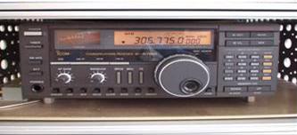
The two ICOM receivers employed are model IC-R7100. After the frequency is set by the SPU, they receive radio waves and send them to the PSK and FSK modems for decoding the satellite data transmissions [Santa Clara, 2002]. The current receivers used are capable of detecting frequencies of 29 MHz to 2.0 GHz. Two receivers are used in order to create redundancy so that if one receiver fails, the other will continue tracking. These will be replaced with receivers capable of reading L-Band (1.2 GHz) and S-Band (2.4 GHz) frequencies in semesters to come. A picture of the receiver is shown in Figure 3.2.
The phase shift keying (PSK) and the frequency shift keying (FSK) modems are necessary to encode and decode the satellite data transmissions [Cross, 2002].
The precision standard clock is vital when tracking a satellite because it determines the exact time, within one second, in order to determine the real-time position of the satellite within 10 degrees.
The Doppler Corrector Unit will adjust for the accurate Doppler shift based on the satellite’s velocity as seen by the observer, which is the tracking station. Doppler Shift is caused by the relative motion between a satellite and an observer, which causes a frequency shift known as the Doppler Effect. [Doppler Compensation, 2003]
The satellite tracker unit is located within the SPU and enables the antenna rotator to be controlled by the satellite tracking program, STK. It is the link between the computer and the antenna controller. [Cross, 2002]
Applied Research Laboratories donated additional hardware for current semester use only. The donated equipment below was not integrated into the final ground station, but was utilized for experimental and testing purposes.
· DAIWA 144/444 MHz Antenna Tuner
The antenna tuner can tune frequencies in the Ultra High Frequency band of 144 or 444 MHz.
· Preamps 400-450MHz 10 in 100 out
This preamp amplifies the weak signal from space, in order to get a clear and processable signal.
· ICOM IC 218H 144-150 MHz Transceiver
This transceiver is capable of transmitting and receiving data over frequencies ranging from 144-150 MHz. All of these components acquired from ARL can be found in Figure 3.3.
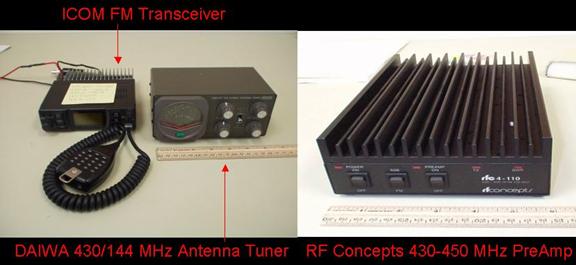
Figure 3.3: ARL Equipment
Currently, LTS is using Satellite Toolkit (STK) to retrieve the most recent orbital elements of a satellite to be tracked. A preliminary LabVIEW interface has been designed that retrieves the orbital elements and launches STK. STK was chosen to propagate satellite orbits because it was easily accessible and UT students are familiar with the software. It is not necessarily, however, the best software available for the capabilities that LTS would eventually desire. In future semesters, as LTS joins the Santa Clara ground network, LTS will transition to a more user friendly software with web capabilities, such as the software that RSL employs.
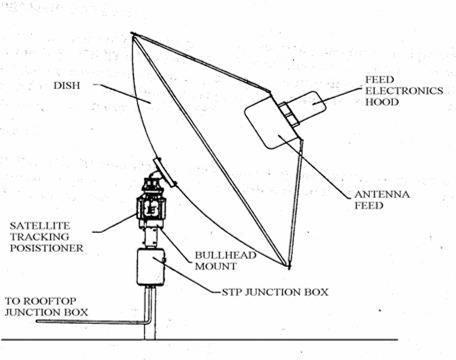
The rooftop components consist of cabling, junction boxes, and the dish system. Figure 5.4 illustrates the assembled dish system and its components. The following section will describe the individual rooftop components and their functions as part of the satellite tracking station.
The control room system and the rooftop system are connected by 120 feet of cables. Two gray coaxial cables, three red nine-wire data cables, and two red three-wire data cables run from the Satellite Design Lab to the top of the roof. The RG58 coaxial cables transmit radio frequency signals, and the RF shielded data cables transmit information, as to control dish orientation. All cables are plenum rated, which means they are fire proof.
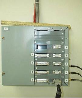
These cables connect the signal processing system (SPS) junction box inside the lab to the rooftop junction box. As seen in Figure 3.5, The SDL junction box has accommodations for up to nine connectors; although only seven wires are currently implemented. A detailed diagram of all pins connections and wiring configurations is provided in the appendix. This diagram will make it possible for future groups to understand the wiring layout of the satellite design lab and rooftop system.
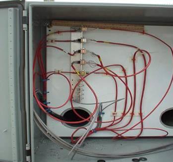
The rooftop junction box and the satellite tracking positioner (STP) junction box are connected by thirty feet of conduit encased cables that are bolted to tracks on top of the roof. The cables are encased in 1½ inch EMT waterproof conduit, and are plugged into connectors inside the rooftop and STP junction boxes. Figure 3.6 shows the rooftop junction box and the cables that run from the SDL junction box and then continue to the STP junction box.
The STP junction box is attached to the mast of the dish about two feet from the ground. The mast and dish base are made of galvanized steel, and the dish base is bolted to the roof. Located inside the STP junction box are three power supplies, a connector bulkhead, and a microcontroller based positioner control board, as shown in Figure 3.7. The first power supply is a 24 Volt DC linear supply that delivers power to the rotors that control the azimuth and elevation, elevation head solenoids in the satellite tracking positioner, and the positioner controller board. A 15 Volt DC linear supply and a 28 Volt DC switching supply deliver power to the hood electronics. [“MightySat-Installation”, 1996]

The bullhead mount is attached to the mast above the STP junction box and is used as a support structure for the satellite tracking positioner. It has a lower cylindrical portion that bolts directly to the mast. The upper portion of the mount is hollow and allows for clearance of the motor in the satellite tracking positioner during azimuth rotation. The circular top of the mount attaches to the bottom of the positioner with four 0.515 inch bolts. [“MightySat-Installation”, 1996]
The satellite tracking positioner controls the azimuth and elevation position of the dish. The weight of the antenna dish, its corresponding components, and wind create a load which must be overpowered by the elevation and azimuth motors. The bottom portion of the positioner, as shown in Figure 3.3, houses the elevation and azimuth drive motors, gear boxes, and drive gears. Each drive motor has micro switches for determining limit positions and incremental encoders for positioning. Cables run from the bottom portion on the positioner to the elevation head and to the STP junction box. These cables carry solenoid drive pulses, lockpin position information, and azimuth and elevation position signals. Table 3.1 displays the specifications on the satellite tracking positioner. [“MightySat-Installation”, 1996]
|
Specification Description |
English Units |
Metric Units |
|
Total Bending Moment |
600 ft-lbs |
83 kg-m |
|
Total Vertical Load |
6,000 lbs |
273 kg |
|
Delivered Torque |
400 ft-lbs (El) 200 ft-lbs (Az) |
56 kg-m (El) 28 kg-m (Az) |
|
Withstand Torque |
600 ft-lbs (El) 300 ft-lbs (Az) |
83 kg-m (El) 42 kg-m (Az) |
|
Elevation – through zenith (limit-to-limit travel) |
180 deg |
same |
|
Azimuth (limit-to-limit travel) |
342 deg |
same |
|
Velocity |
2.0 deg/sec (max) (El) 2.5 deg/sec (max) (Az) |
same |
3.3.5 Antenna Dish
The antenna dish used for the Longhorn Tracking Station is a three-meter diameter, commercial, wire mesh dish. The dish was received in four sections, which were bolted together to form the complete dome, as shown in Figure 3.8.


The RF feed is composed of the hood electronics and the feed elements, as shown in Figure 3.9. Weather resistant fiberglass radomes cover the RF feed, which is mounted to the dish at the vertex focal point of the antenna. Cables run from the RF feed to the STP junction box and help form a connection from the feed electronics to the SPS junction box in the control room. The LTS team is rebuilding the RF feed in order to track S and L-band frequencies, and is using the MightySat feed as a model.


It was necessary to find a new feed element design that was capable of tracking S/L band frequencies. An article written by Gerald R. Brown was found in The AMSAT Journal that detailed the design of an easy-to-duplicate dual band antenna. The antenna is mounted on a 15.5 cm diameter paint can cut 1.5 cm deep. The L-band reflector is a 6” x 6” double-sided circuit board, and the L-band patch is made of a 26 gauge copper sheet. The S-band antenna is also made of 26 gauge coppers sheets. The materials for the feed have been purchased and are currently in the WRW machine shop. Figure 3.10 is a photo taken from Brown’s article of the completed feed. The completed feed element has a diameter of six inches and will be attached to one side of the two-foot diameter aluminum plate.

Figure 3.10: S/L-Band Feed [Brown, 2003]
The hood electronics are mounted to the opposite side of the aluminum plate. The layout of the electronics is much like that of the MightySat feed, but components such as S and L-band amplifiers are added in order for the system to track these frequencies.
Like many other outdoor structures, it is necessary for the dish system to be grounded. Lightening or other electrical surges can cause structural failure, fires, and serious damage to system electronics. In order to ground the system, a braided wire rope has been run from the base of the metal dish to a metal clamp on the conduit. This will enable unexpected surges of electricity to be discharged safely from the structure [Cross, 2003]. The rooftop grounding can be seen in Figure 3.11.
3.3.8 Balance and Safety Chain
Weights have been installed on the dish to reduce the torque needed to move the dish in azimuth and elevation. Two sets of twenty-pound weights were attached on either side of the dish above the satellite tracking positioner to reduce the stress on the elevation head. A braided steel safety chain was installed to prevent dish flyaway in the case of strong weather conditions. The chain connects the mast and bar on the dish and can be seen in Figure 3.11 along with the balance weights.

Figure 3.11: Grounding, Balance, and Safety Chain
In the quest for LTS to become a part of the Santa Clara University ground station network, Santa Clara University has agreed to acquire new tracking equipment for LTS. In order to increase data availability, it’s important to have an operational ground station in Central North America; Austin is an ideal location. Santa Clara University will purchase equipment in order to expand LTS capabilities. For this reason, LTS will be modeling much of our future tracking equipment after that of Santa Clara University.
This section details the equipment that will be integrated into the Satellite Design Lab once obtained by SCU. The hardware is due to arrive in the months of June and July of 2003.
Currently, there are two computers needed to operate the ground station: a mission planning computer and a tracking computer. One of the two computers will be eliminated to create a more concise system that is capable of joining the mission planning and signal processing unit.
The ICOM IC-R7100 receivers currently in place in the LTS ground station are only able to receive data. In the long run, LTS would also need a transmitter in order to uplink commands to a satellite. The ICOM 910 Transceiver, seen below, will allow LTS to both uplink commands to and downlink data from the satellite once set to the appropriate frequency.

Figure 4.1: ICOM 910 Transceiver [ICOM, 2003]
In the future, the PSK and FSK modems will be replaced by a
Kantronics 9612 Plus Packet Creator, or modem (Figure 4.2). This will
both encode transmissions sent from the ground to the satellite and
decode transmissions sent from the satellite to the ground. It is also
capable of receiving commands from LabVIEW. [Santa Clara, 2002].

Figure 4.2: Kantronics 9612 Modem [Kantronics, 2003]
The current SPU is operated by DOS. The SPU is set up to take satellite data from the mission planning computer that has been calculated with STK and then point the dish toward the satellite. The SASI satellite tracker will be employed in the upcoming months. This tracker enables the antenna to be rotated according the satellite positioning software; this controller could also eliminate the need for two computers.

This controller is pre-packaged and comes with software for controlling and integrating with the hardware and other software. The SASI sat controller is also extremely compatible with the Kantronics modem.
LTS is currently running STK to propagate orbits in order to get the azimuth and elevation of the satellite in view. While STK is a powerful tool and a robust option to consider for satellite propagation software, it is a complicated program, and there are other viable options available. Santa Clara University and The University of Hawaii, for instance, use Nova software to find the azimuth and elevation. For later use, LTS may consider switching to Nova in order to use common software between all of the ground stations in the network; Nova works well with the SASI Sat Controller mentioned above. Santa Clara University RSL set up a network, which entails a long and complicated installation process, but benefits multiple users nationwide. In the future, LTS may also consider setting up a system that can be accessed through the Internet.
Santa Clara University RSL set up Internet connectivity for remote access so that each participating station could remotely log on to other stations. Access to each ground station will be limited to users that are deemed valid through an application process. Users will be limited to licensed HAM radio operators in order to reduce the misuse of the stations. Once users submit an application, the Administrator of each ground station reviews the application, and if granted access, they will be assigned a priority level. Valid users need only go to the scheduling page and schedule station time. Users of the web system will employ the LabVIEW interface to connect to the remote ground station during their verified scheduled times [Cross, 2002]. When LTS joins the ground station network in future semesters, we will also be accessible through the Internet, and users will have the option of logging on to the LTS.
The three-meter diameter dish on the roof of WRW will not be able to capture satellite data over every amateur radio band. Therefore, in the future several Yagi antennas will be mounted adjacent to the dish. These antennas will be responsible for tracking over 1.2 GHz, 440 MHz, and 144 MHz. The first Yagi to be installed on the roof, will duplicate the 12 foot Yagi antenna on the roof at Santa Clara University; as seen in Figure 4.4. This Yagi is capable of tracking both S and L bands given the proper amplifiers. There will also be a rotor controlled by the SASI sat controller that moves the antenna in azimuth and elevation.

Figure 4.4: Yagi Antenna and Rotor
This section outlines the cost of the current and future equipment previously described in the sections above.
The MightySat equipment donated by the United States Air Force has both rooftop and satellite design lab components. These components include: the dish, the mast, the STP junction box, the satellite tracking positioner, the Mission Operations Tower, the receivers, the modems, the SPU computer, the precision standard clock, and the power unit. The cost incurred by the Air Force at the time of procurement was approximately $35,000. The current value of the MightySat equipment is approximately $5,000.
The equipment that Santa Clara University is purchasing for LTS is currently on order. This equipment includes: the 12’ Yagi antenna, the antenna rotor, the tranceiver, the modem, the satellite controller, and the software. These components have an approximate value of $8,000. A detailed component list was created to be implemented in the ordering process. This list includes items currently common to both stations, and items that are unique within each station; this list can be found in the Appendix.
After acquiring the MightySat equipment, The University of Texas charged the Aerospace Department $20,000 to assemble and install the equipment on the roof of WRW. A guard rail around the perimeter and a stair rail were necessary safety precautions that cost $2,100 and $3,500, respectively. To run the cabling from the 4th floor of WRW to the roof cost $4,500. During this installation process, an engineer was consulted, which cost $4,000.
All of these various costs bring the LTS to a total value of approximately $47,100. A description of these costs can be found in Table 5.1, below.
|
ITEM |
COST ESTIMATE |
|
MightySat Equipment (Current Value) |
$5,000 |
|
Santa Clara Equipment |
$8,000 |
|
Dish Installation |
$20,000 |
|
Guard Rail |
$2,100 |
|
Stair Rail |
$3,500 |
|
Consulting Engineer |
$4,000 |
|
Cabling |
$4,500 |
|
TOTAL |
$47,100 |
The following section details the progress that has been made in the spring 2003 semester to the midterm point and also through the remainder of the semester.
The Longhorn Tracking Station team began the semester by researching the tracking stations that LTS will network with in the future. Research was also conducted to learn the basics of radio science and the necessary components of an amateur radio band tracking station.
We also researched various S/L-Band antenna feed designs in order to find a design that met the requirements and limitations set by the LTS. To anticipate the final design, a new aluminum plate was duplicated to serve as a base for the feed. In our research, we found that antenna feed design is more “black magic” than science. Many of the designs are made of common household items such as paint cans, and coffee cans. The dimensions of the antenna feed components must be accurate to 0.5 mm in order to ensure proper tuning. If the dimensions are imprecise, resonance may occur.
Much of the semester was spent on wiring; wiring on the roof began by measuring conduit, coaxial cables, and data cables to run from the rooftop junction box to the satellite tracking positioner junction box. Connectors were soldered to both ends of the three and nine wire-data cables to match existing cables already installed from the Satellite Design Lab to the roof and also installed in the satellite dish tracking positioner junction. The MightySat equipment was not delivered “plug and play”, as expected. Over years of weathering, the connectors had rusted and wires were damaged and others were severed when they could not be easily taken apart. Thus, the wiring had to be traced back to the source using vague user’s manuals.
In order to obtain additional equipment, a hardware list was compiled and sent to SCU so that those involved could purchase the remaining components. In addition to those components, arrangements were made with Applied Research Laboratories to acquire hardware including transceivers, a preamplifier, and an antenna tuner. A tour of ARL’s Global Positioning System station was scheduled to better understand the components of an operational tracking station.
Beginning mid-March 2003, we finished soldering, wiring, and labeling all the cables from the Satellite Design Lab to the rooftop junction boxes. Soldering was a new skill that had to be perfected during the first month of the project. It is a very tedious task that was made more difficult by the rooftop conditions. We checked for continuity between the roof and satellite design lab, and the two rooftop junction boxes to ensure that the cables were correctly configured and the circuits were completed. Continuity was checked with a BK Tool Kit voltmeter, and it was confirmed that all wires were properly soldered and there was no cross wiring. A wiring diagram was created so that future semesters can alter and expand the path of circuitry.
We acquired the hardware from ARL that was promised earlier in the semester; this hardware was used for experimental and testing purposes. Each component was observed in order to understand the capabilities and operational performance.
Grounding was implemented in order to avoid electronic shortages due to lightning or other power failures. The Mission Operations Tower in the Satellite Design Lab was grounded to the ceiling with braided wire rope. The rooftop dish was also grounded to the conduit with a weather proof braided wire rope.
To reinforce the dish in case of high winds and harsh weather, a safety chain was attached from the dish to the ground base. A crack propagated on the structure of the dish and was reinforced with a piece of aluminum machined in the aerospace machine shop. Also, twenty-pound weights have been installed on each side of the dish in order to reduce the rotational torque upon the satellite tracking positioner.
The final act of business for the semester was to decide upon an antenna feed design. The detailed design is currently in the machine shop. Since the components are unprepared for construction, the antenna feed has not yet been assembled. After assembly, the measurements will need to be checked in order to ensure that the antenna is tuning to the desired frequencies, and that there is not resonance.
There are additional goals that extend outside of the time frame of the current semester. As first priority, the software and hardware components must be integrated prior to tracking satellites.
Due to missing software on the signal processing computer, integration of the software and hardware components was not completed this semester. The software that allows communication between the SPU and the mission planning computer and also allows the SPU to communicate with the satellite tracking positioner, on the roof, was removed prior to the Air Force’s donation. Much of the semester was spent attempting to find documentation about the communication data strings, and then to recreate the software. The manufacturers of the software are no longer in business, which made obtaining the software user’s manual extremely difficult. The manual has been ordered, and upon arrival attacking this problem should be a priority. If it is not possible to recreate the missing data strings, a new controller will need to be procured.
Once the computers can communicate with the hardware, satellite tracking can occur. Modifications must then be made to increase our frequency range and operational efficiency. Additional frequency ranges will be added in order to track other amateur radio bands, as described in the radio science section.
Once the tracking station is efficiently operating within the desired capabilities, the software can then be enhanced in order to automate the tracking process, which involves automating the receiver frequency setting, Doppler corrector, and satellite dish orientation. These processes will be computerized with the aid of a LabVIEW software interface. Adjustments will be made enabling the tracking station to uplink commands to university-owned satellites as well as downlink information from UT and amateur satellites. Uplink capability will be vital in satellite guidance, navigation, and control.
Finally, the university intends to join the already existing network with Santa Clara University and the University of Hawaii. This will allow all linked stations to obtain satellite data for a longer duration through the satellite orbit. This process will include a time consuming installation of web interface software that allows users to logon to remotely, and installation of new security measures.
This section includes the management organization of the Longhorn Tracking Station team, as well as the schedules and deliverables for LTS throughout the remainder of the spring 2003 semester.
The Longhorn Tracking Station team is made up of advisors and students. The professor in charge of the tracking station is Dr. Glenn Lightsey. Working under Dr. Lightsey is Tom Campbell, who is a senior aerospace student serving as the supervisor of the student team. The LTS group leader is Stephanie Autrey, as shown in the organizational chart below. Stephanie is a Systems Integration Engineer, and she manages all of the equipment for the fourth floor ground station control room. Stephanie made arrangements for the LTS group to tour the Applied Research Laboratories (ARL) ground station. Her association with ARL has been instrumental in helping the LTS group with donated equipment and time.

Sarah Stojanik is a Senior Hardware Engineer working on the LTS. She is in charge of the equipment on the roof of WRW, including the dish, the feed horn and junction boxes. Erin Miller is the second senior aerospace engineer working on the LTS. Erin is responsible for helping with software integration. She is aiding in acquiring future equipment from Santa Clara University, and documenting wiring.
The LTS group has already made a great deal of progress in preparing the ground station for operational use. However, there are still many goals to achieve in the semesters to come. There are several project deliverables for this semester that can be found in the table below.
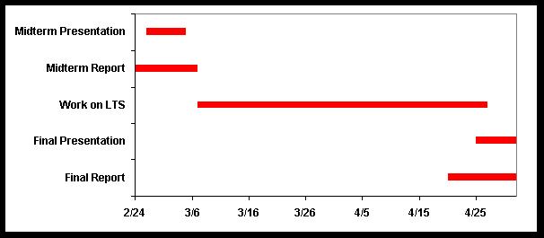
Figure 8.2: Schedule of Deliverables
The LTS mid-term presentation took place on March 5, 2003, and our mid-term paper was due March 7, 2003. Between the mid-term paper and final presentation the LTS group continued making progress towards semester goals for the ground station. The final presentation occurred April 28, 2003, and the final report was due on May 5, 2003. After completion of the LTS semester goals, the project will continue for semesters to come.
“Amateur Radio Bands,” University of Texas Amateur Radio Club. http://www.utexas.edu/students/utarc/license/bandplan.html (1 March 2003).
Brown, Gerald R., “Build This No-Tune Dual-Band Feed for Mode L/S,” The AMSAT Journal, Feb 2003.
“Doppler Compensation,” Doppler Corrector. http://www.orbitessera.com /html/doppler_compensation.html (28 Feb. 2003).
Cross, Trevor , Eric Hornisher, Michael MacKinnon, Dave Masuda, Daniel Oranen, and Zac Randles. “RACE: Remote Accessible Communications Environment,” Santa Clara University, 11 June 2002. http://hubbard.engr. scu.edu/docs/thesis /2002/Race.pdf ( 20 Feb. 2003).
“ICOM: VHF/UHF Amateur Multi Mode Transceivers,” Universal Radio Incorporated. http://www.universal-radio.com/catalog/hammulti/1910.html (1 March 2003).
“Kantronics KPC-9612+ Packet Communicator,” Kantronics. http://www.kantronics.com/kpc9612+.htm (1 March 2003).
Mach, Rick. “NIMA Monitor Station Network (MSN) Overview of Charts.” Applied Research Laboratories. Austin, TX, Aug. 2002.
MightySat-I UHF Ground Terminal User’s Manual for Operational System. 30 September 1996.
MightySat UHF Ground Station Installation Manual. 6 August 1996.
“Radio Frequencies: How Radios Work,” How Stuff Works. http://electronics.howstuffworks.com/radio-spectrum1.htm (2001).
“SASI Sat Controller,” Northern Lights Software Associates. http://www.nlsa.com/ (1 March 2003).
Wiring Diagram

Parts List

Satellite Tracking Flow Chart
