How to Use the WinOncore™ Software with the PowerStrike Receiver
WinOncore Commands
Click on an icon below to learn more about that feature.
![]()
![]()
Large Button Bar Commands
The OPEN command is only available based upon which view window you have selected. It can only be used when
- The Survey Window is active
- The Command Window is active
- The Satellites Window
(Azimuth) is active
When the Survey Window is open you can load path files (" .pth ") that have been previously saved. Path files save the information currently displayed in the Survey Window.
When the Command Window is open you can save the command window output as a log file (" .log "). This is the same as right-clicking in the command window and starting a log from the menu options. NOTE: Although this is an OPEN command, you are really SAVING the command window output, but note that the SAVE option is not available from the titlebar. I believe this is a software bug.
When the Satellites Window is open you can load mask files (" .msk "), which contain previously saved satellite mask angle information.
Similar to the OPEN command, the SAVE command is only valid for the three windows described in the OPEN command. You can save the information for these windows with this command and use the OPEN command to retrieve that information.
The Signal Quality Window displays all of the channel dependent data from the Position/Status/Data Message (@@Ea - 8 channel, @@Ha - 12 channel). This display includes a bar chart representation of the signal strength. The right mouse button over this window gives access to the following Signal Quality Properties:
Reset observed Min/Max: This action will reset the scale of the signal Quality Window to the maximum and minimum signal strengths observed in the current session.
Properties: This option brings up a dialog box where the user can set a threshold for the minimum and maximum signal strengths observed in the Signal Quality Window when the Autotrack box does not have a checkmark by it. Otherwise the length of the signal strength bars will adjust to the minimum and maximum values observed in the current session. The observed minimum and maximum values for the current session are also listed in this dialog box. Note: To see the Signal Quality Window update when playing back data, assure that the autotrack box has a checkmark by it.

When a satellite is tracked the receiver reports the corresponding carrier to noise density ratio (C/No) in dB-Hz. The height of the bar represents the magnitude of the signal strength. Satellites that are being tracked but are not yet being used in the position solution (mode is 7 or less) are indicated with a gray signal strength bar. Satellites that have reached mode 8 are used for the position solution and are indicated with a blue bar.
PRN: The satellite ID number assigned to the channel.
MODE: The satellite tracking Mode number ranges from zero to eight. Each value represents a step in the acquisition and tracking process. The important modes to consider are five, seven, and eight. Mode five indicates that the channel is locked onto the satellite code and range measurements are available. Mode seven means that the ephemeris is currently being downloaded. Mode eight means that the ephemeris has been downloaded and the channel is locked onto the navigation data message. In order for a satellite to be used in the position solution, it must be tracked at mode five or higher and the ephemeris must be available. In order for a satellite to be used in the precise time solution, it must be tracked at mode eight.
Channel Tracking Mode
0 - Code Search 1 - Code Acquire 2 - AGC Set 3 - Freq Acquire 4 - Bit Sync Detect 5 - Message Sync Detect 6 - Satellite Time Available 7 - Ephemeris Acquire 8 - Available for Position STATUS: The channel tracking status byte has several independent flags pertaining to the satellite. The PowerStrike has a 2 byte channel status flag. When bit seven is set it indicates that the satellite being tracked is being used for the position fix. The signal strength bar will be blue when bit seven is set, and gray when it is clear. If a satellite becomes unhealthy, bit four will be set, the signal strength will turn gray and the satellite will be removed from the position solution. The other satellite bits are provided for information; refer to the Users Manual for details.
The Navigation Window displays the date, time, position data, receiver status and visible satellite status. This information is extracted from the Position/Status/Data Message (@@Ha - 12 channel). When viewing NMEA messages, only the date, time, and position data will be updated as provided from the GSA message.
The Receiver Status is reported in the hex format. Critical status indicators that have their flags set to True will be reported below this heading. The possible receiver status messages are as follows:
- Fast Acquisition Position
- Filter Reset to Raw GPS Solution
- Cold Start
- Differential Fix
- Position Locked / 3D Fix
- Insufficient Visible Satellites
Navigation Window Properties: The right mouse button over this window gives access to the following Navigation Window Properties:
Set Position: This option brings up a dialog box where the user can enter the initial position for the antenna as well as indicate whether the position should be applied to position hold. This option can also be invoked with the "set position" button on the small toolbar.
Enable Position Hold: When Position-Hold is enabled, there will be a checkmark beside this option. Position-Hold is commonly used in timing applications. Note that the coordinates for the Position-Hold must be specified before the Position-Hold mode is enabled. Unfortunately I could not get this feature to work properly for the PowerStrike Receiver.
Enable Site Survey: There will be a checkmark beside this option when the Automatic Site Survey is enabled. While in survey mode, a flag will be set in the Position/Status/Data Message (@@Ea). When the survey is complete, that flag will clear, the surveyed position will be automatically entered into the Position-Hold Position fields, and the Position-Hold Mode will be enabled. Unfortunately I could not get this feature to work properly for the PowerStrike Receiver.


The survey window displays the 2-dimensional survey path (latitude vs. longitude) in window 1, altitude (GPS height) path in window 2 and statistical information on the position average in window 3. The entire Survey Window with its current information can be saved and loaded for later analysis. The Save option is found under the File Menu or the large Save icon below the menu bar may be selected. The Survey Window information will be saved as a *.pth file. To load a pth file, there are the following options: File Menu > Open, Open icon, or Survey Window Properties > Open.
2D Position Plot: The 2D position plot shows the path of the receiver as computed from the Position/Status/Data Message (@@Ha - 12 channel). It is a plot of latitude versus longitude. As the area of the path increases, the plot will rescale itself. The plot only shows an approximation of the perspective; it assumes that the distance between degrees of latitude and longitude is constant. Of course, the distance between degrees of longitude decreases substantially when one is further away from the equator. The distance between two points can also be measured from the 2D position plot. There is an x in the position plot that is set by clicking a starting position on the plot with the left mouse button. As the mouse is moved away from this marker, the distance is measured and displayed in the status bar at the bottom of the main WinOncore12 window. NOTE: The distance is calculated assuming that the earth is a perfect sphere so the distance presented is only a rough estimate of the true distance. As the mouse crosses over the 2D position plot, the latitude and longitude of the current mouse position is also displayed in the status bar.
Altitude Profile Plot: The altitude profile plot shows the profile of the receiver path based on the reported GPS height in the Position/Status/Data Message (@@Ha - 12 channel).
Statistical Data: The Statistical data is most useful in a stationary application where the effects of SA can be analyzed. There are two types of statistical calculations performed on the position data from the Position/Status/Data Message. The mean average is a standard running average (sum of the data/samples). The Least Squares Average is calculated using curve fitting best fit method. Apart from being calculated in the Statistical Data frame, the statistical data can also be represented graphically in the 2D position plot. The standard deviation shows the one sigma (68.27%) reliability that the position is within this error ellipse as defined by either statistical computation.
Printing: The Survey Window can be printed when it is the active window. The Print option under the File Menu is made available and a print preview may also be selected. The printout will contain all three Survey Window frames.
The right mouse button over this window gives access to the Survey Window Properties:
Open: Opens a previously saved path (*.pth) file.
Erase and Clear Screen: If Erase and Clear Screen is selected under the options, the standard deviations and number of samples will be reset to zero and the calculations will begin again from the time it was reset. All plots in the Survey Window will also be cleared.
Enable Least Squares Fit Average Indicator: This indicator, when enabled, will be represented by a black line in the Altitude Profile and by a black ellipse in the 2D Position Plot. The size of the ellipse is based on the standard deviation calculated for the latitude and longitude. The least squares average is the center X of the ellipse. The thinner black line centered between two bold lines on the Altitude Profile indicates the Altitude (GPS height) average.
Enable Position Average Indicator: This indicator, when enabled, will be represented by a green line in the Altitude Profile and by a green ellipse in the 2D Position Plot. The size of the ellipse is based on the standard deviation calculated for the latitude and longitude. The least squares average is the center + of the ellipse. The bold green line on the Altitude Profile indicates the Altitude (GPS height) average.
Properties: This action brings up a dialog box with three tabs:
- Position Plot Tab: The purpose of this tab is to set how the two plots display data.
- Enable Position Acquisition: When not enabled, the survey window will stop calculating statistics and cease output on the plots. When this option is again enabled and provided the survey window has not been cleared, the calculation of the statistics and the plots will retain the information from before Position Acquisition was disabled and will then continue position acquisition. The position information from the time that the Position Acquisition was disabled to when it was again enabled is disregarded.
- Plot Indicator: The Small and Large radio buttons sets how each position point is represented on the Altitude Profile Plot and the 2D Position Plot. The Use Lines option will draw a line between each position point on the plots.
- Lat/Lon/GPS Height Average Calculations Tab: The position averages are based on the DOP threshold set in this tab. When a DOP is greater than that set in this tab, the position is not used in the calculation of Averages. The plots will indicate this occurrence with red position points/lines instead of the standard blue.
- Printing Tab: As mentioned above, the print option will print out all three frames of the Survey Window. The purpose of this tab is to add additional comments to the Survey Window when it is printed. These comments will be included in the bottom text region of the plot.


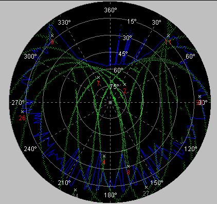
The Azimuth and Elevation Window (shown above) contains a skyplot of all visible satellites according to their elevation and azimuth. The Satellite Info tab displays information for each satellite including the PRN, Doppler, elevation and channel status of all the visible satellites. It also shows the signal strengths for the satellites currently being tracked and lists any ignored satellites and the mask angle.
The skyplot will only show visible satellites once an almanac is loaded into the receiver. The receiver must also be sending the Satellite Visibility (@@Bb) message to update any information in the Azimuth & Elevation Window. The satellite text color is red when it is used by for the position computation. Satellites not used by the receiver are indicated with gray text.
Skyplot Properties
Open This option opens a previously saved Physical Mask Angle.
Enable Satellite Trails: A checkmark beside this option indicates that the satellite trails are shown on the skyplot. The satellite trails are displayed in green (as shown above) and represent the path of each satellite. To disable the satellite trails, choose Enable Satellite Trails again.
Clear Satellite Trails: This option clears the skyplot of all satellite trails.
Enable Physical Mask Angle: A checkmark beside this option indicates that the physical mask angle is shown on the skyplot. A blue polygon on the skyplot represents the physical mask angle. Choose this option again to remove the physical mask angle from the plot.
Clear Physical Mask Angle: By choosing this option, the physical mask angle will be cleared and the calculation of a new physical mask angle will start over.
Enable Satellite Details: The satellite details show the azimuth (A) and elevation (E) below the PRN of each satellite. When there is no checkmark by this option, the number below each satellite is the PRN.
Properties:
- Physical GPS Mask Angle Tab:
- SNR Threshold: The Physical Mask Angle is determined by using the azimuth and elevation of satellites that have a signal strength above the SNR threshold and a true solution flag. The SNR threshold is set here. A high SNR threshold may show an elevation mask is shorter time.
- Comment: The comment field allows extra information to be described above the Physical Mask Angle plot when it is printed. This gives a perfect opportunity to describe the antenna position and to add additional notes.
- Autoload Tab:
- Enable Auto Load: The Physical Mask Angle can be saved by choosing the Save icon or File Menu > Save. This feature allows the mask angle to be opened in another session so that it may be continuously built upon or used to imply an antenna installation. When Enable Auto Load is checked, the *.msk file indicated in the filename field is opened automatically upon starting WinOncore12. The Browse button can be used to navigate to the desired file.
The Satellite Information tab contains a table that shows the individual satellite information as decoded from the @@Bb message.
Tracked Satellites: Tracked satellites are those that the receiver is currently tracking according to the field in the Position/Status/Data Message (@@Ha - 12 channel). In order to be considered tracked, the satellite mode must be five or greater.
Visible Satellites: Visible satellites are those that are above the horizon based on the current position, date, time, and almanac. This value is reported in the Position/Status/Data Message. If there is no almanac in the receiver memory, the number indicated for visible satellites will read 0. The receiver will attempt to track the satellites that have the highest elevation angles to fill its channels. Satellites that are low to the horizon may not actually be visible due to blockage from buildings, trees, or terrain.
Mask Angle: The mask angle that was set through either the Additional Message Window or through the Satellite Settings Dialog is shown here.
Satellite Ignore List: The satellites included in the ignore list are displayed under this heading. The satellite ignore list is set through the Additional Message Window or the Satellite Settings Dialog.
What is this Physical Mask that is referred to time and time again? Well, the Physical Mask Angle is a graphical representation of the satellites that can be tracked with the antenna in its current location based on the azimuth and elevation of the satellites that have been tracked in the past. It gives an indication of the stationary antenna installation by showing where satellites can and cannot be tracked. The blue outline on the figure below is the physical mask (or masking) of the GPS signal as "seen" by the GPS antenna.
A physical mask angle with a small coverage area implies an obstruction or poor antenna installation. If the antenna has a clear, unobstructed view of the sky, the Physical Mask Angle will indicate a large coverage area. The Physical Mask Angle is outlined as a blue polygon and is overlain on the Azimuth and Elevation Skyplot. It is calculated by checking the signal strength and solution flag from tracked satellites. If the solution flag for a satellite is set to true and the signal strength is above the SNR threshold then the azimuth and elevation of this satellite is included in the physical mask angle. The SNR threshold is set in the Azimuth & Elevation Property Sheet. To achieve a good representation of the Physical Mask Angle, allow the receiver to track over a 12-hour period.


The Command Monitor Window displays all commands sent (TX) to and received (RX) from the Oncore GPS receiver, including NMEA messages. The following command monitor properties are accessed through the right mouse button when it is over the Command Monitor Window:
Start Log File: The option will open a Save As dialog box where the user is prompted to enter a file name. The default extension for this file is *.log. This log file is an ASCII file that only contains the messages displayed in the Command Monitor Window.
Close Log File: Closes the log file.
Pause: This option causes the Command Monitor Window to stop outputting messages. Note that the receiver is not affected by this command. The pause option is useful when an anomaly is observed and a closer inspection of the message is immediately desired. When this screen is paused, it is easy to select and copy messaged to Notepad or Word. The cut, copy, and paste options are also available in the command monitor properties.
Erase Screen: Erases the messages displayed in the Command Monitor Window.
Command Filter:

The command filter is only available for the Command Monitor Window. It contains a list of all the Motorola binary messages listed in the Command Manager. The purpose of this option is to control which messages are viewed in the Command Monitor Window. It will NOT affect what is being sent from the receiver. This feature is particularly beneficial in isolating particular messages for analysis. For messages that you do not want to view or record in the Command Monitor Window, simply select the message in the Enable area and choose Disable. Note: The command filter is only available for Motorola Binary output.


The additional message window acts as a direct communication link with the receiver. All Motorola binary commands (minus the checksum) can be sent from the command line of this window. The response is displayed in the bottom gray scroll area. The English commands described in the users manual can also be typed and sent from this window. The response message can be customized through the Command Manager that is accessed from the right mouse button menu or from the Options Menu. Any text displayed in the response section can be copied and pasted to another application (ie. Notepad). Text can be copied from, or pasted to the command line prompt. If commands have previously been entered, the auto-completion feature of the command line drop-down scroll will end an entered command with the previously entered data. To ignore the auto-completion, simply continue type the remainder of the message. All commands entered in the current WinOncore12 session are saved in the command line drop-down list .

The Timing Window displays most of the data from the Time RAIM Setup and Status Message (@@En and @@Hn). There are two tabs in the Timing Window. The Time and TRAIM Status tab displays the TRAIM Status, Time and Oscillator and Clock Parameters. The Negative Sawtooth tab displays the negative sawtooth time error of the next 1PPS pulse as a line graph. Note that if the Leap Second Pending Status Message (@@Gj - 12 channel) has not been polled, the leap second pending status will be invalid.
NOTE: The PowerStrike receiver does not have the TRAIM (Time Receiver Autonomous Integrity Monitoring) ability. Although the WinOnCore software supports this option, since the receiver does not support TRAIM, it will not be discussed.
Negative Sawtooth Plot does not apply to this receiver.

Display of the ABOUT screen for information pertaining to the WinOnCore software.
When you click on this button, it give you a mouse pointer with a question mark next to it. After clicking on this button, click on any other button to get help with that button. If all else fails, you can get help using the WinOnCore software by choosing HELP > Help Topics from the menu bar as shown below.

Small Button Bar Commands
Playback
/ Record Toolbar ![]()
During playback, this button action moves the file pointer to an earlier position in the file, from which, playback continues.
This button is down when a file is open and in playback mode.
This button temporarily suspends the playback.
During playback, this button action advances the file pointer to a later position in the file, from which, playback continues.
All playback is stopped and the file is closed. This button is also available to stop the recording of a *.bin or *.gps file.
This action opens the Log Raw Data dialog box. Depending on the mode of the receiver (NMEA or Motorola Binary), a filename is entered and saved with the correct corresponding extension. Record is only available when live data is being received from the receiver.
The Playback Status shows the file size (bytes) and the portion of the file that has already been processed. This value is also represented by the Progress bar indicating the percentage complete. The slide bar above the progress bar is used to control the playback speed. If there are many processes active on your PC, it may take a few seconds for the program to respond to the change in speed.
This action invokes the Open Dialog Box. Playback will commence upon selecting a file with either a gps or bin extension.
The ON button enables playback mode and stops communication to the connected receiver.
The OFF button disables playback mode and reestablishes communication to the connected receiver.

Action
Buttons ![]()
Allows you to print certain windows of the WinOnCore software.
The Receiver Setup has screens that guide the user through setting up the Oncore GPS receiver for normal operation. Most of the information entered will be retained for the next time the Receiver Setup is used. The setup procedure is as follows:
- Communication Settings
- Enter the com port that the receiver is connected to.
- Set Position
- Enter the latitude, longitude and height of the antenna.
- Set Time, Date and GMT Offset
- Fill the parameters in the Set Date and Time dialog box.
- Message Output Rate
- Specify the output rate for the Position/Status/Data Message.
The button will invoke an information box that contains the receiver ID. The Receiver ID (@@Cj) command can be performed at any time without interrupting the tracking process. The response to the Receiver ID command is an ASCII message containing information about the Oncore receiver in use. The ID information includes the model number and firmware revision as well as the serial number, dates, part numbers, etc. Using the Receiver ID command is one way of distinguishing different Oncore models. This is a convenient way of developing applications to work with multiple types of Oncore receivers. For example, a VP Oncore always has a model number that starts with a B, while GT and UT Oncore model numbers always start with an R and the M12 Oncore model numbers always start with a P. This command does not seem to work with the PowerStrike receiver.
The Set-To-Defaults (@@Cf) command will reset the Oncore GPS receiver memory. WinOncore12 will wait approximately five seconds for the Oncore receiver to respond to the Set-To-Defaults command. If no response is received, check the receiver connections and try again. The default command can also be sent from the command line of the Additional Message Window.
This screen shot above shows the initial state of the dialog box. The Initiate Test button must be pressed to start the Self Test. The self test may take several seconds to complete and a progress box will indicate the percentage to completion. If there is no response to this command, the Self Test Dialog will display no change. If you suspect this is the case, check for the presence of the response message (RX)@@Ia message in the Command Monitor Window. If there is no response in the Command Monitor Window, check the receiver connections and try again.
The receiver can output either Universal Time Coordinated (UTC) or GPS time. UTC is the basic time system used throughout the world. Greenwich Mean Time (GMT) is based on UTC. GPS time is closely related to UTC. The difference between UTC and GPS time is approximately an integer number of leap seconds. Occasionally, UTC requires a leap second in order to stay synchronized with the Earths rotation. GPS time does not have leap seconds, so the difference between UTC and GPS time is subject to change. The Time Mode (@@Aw) command is used to indicate which time system the receiver should use. The time values reported in the output messages will be in the selected time system.
If the receiver knows the date and time, its location, and has a valid almanac, the time to first fix (TTFF) will be faster than the normal cold start. The initial location does not have to be very accurate to be of use. In fact, the approximate coordinates to the nearest degree is sufficient. Entering the approximate altitude has little or no effect on the startup time. The latitude and longitude must be entered in the position format specified in the General Settings. The position is referenced to the WGS-84 datum. Note that the ellipsoid height is NOT equivalent to the height above mean sea level (MSL) commonly used on maps. Ellipsoid heights can differ from MSL heights by 50 meters or more. The latitude, longitude, and height commands are used to initialize the approximate receiver position. If the GPS receiver is already currently computing a 2D or 3D position fix, these commands will echo the computed values.
If the Oncore receiver knows the date and time, its location, and has a valid almanac, the time to first fix (TTFF) will be faster than the normal cold start. To set the time, date and GMT offset:
1. The Time will be filled in using the computer clock.
2. Use the calendar to enter the current Date.
3. Enter the GMT Offset.
4. Choose either UTC or GPS Time
The Almanac is a set of numbers that are used to describe the orbits of the GPS satellites. The numbers are Keplarian orbital elements and are used to predict which satellites are in view given a certain date, time, and position. The purpose of the almanac is to speed up the satellite acquisition process; it is not required for positioning. The orbital information in the almanac is less accurate than the ephemeris, but valid for a longer time (one to two years). When the Load Almanac command is given, you are prompted to enter a file *.alm to upload to the receiver. Choose a file from the dialogue (latest.alm is the default). It is recommended that you record a new almanac each time you perform and extended positioning or site survey. To record an almanac, open the Msg window. The procedure to capture an almanac is to type the following:
- record alm
- @@Be0
- record alm c
The file latest.alm is overwritten with the current almanc data for each satellite as transmitted by the satellites.
The Visible Satellite Status Message (@@Bb) requests the results of the most current satellite alert computation. The response message gives a summary of the satellite visibility status showing the number of visible satellites, the Doppler frequency and the location of the currently visible satellites (up to 12 satellites). This information is displayed in the Satellite Information Tab of the Additional Message Window. The reference position for the most recent satellite alert is the current position coordinates. Note that these coordinates may not compare to the GPS receivers actual position when initially turned on, since the GPS receiver may have moved a great distance since it was last used. In order for the receiver to compute the satellite visibility information, the date, time, position and a current almanac must be loaded into the receiver.


Last Updated: 5/7/2001
P. Svatek